正在加载图片...
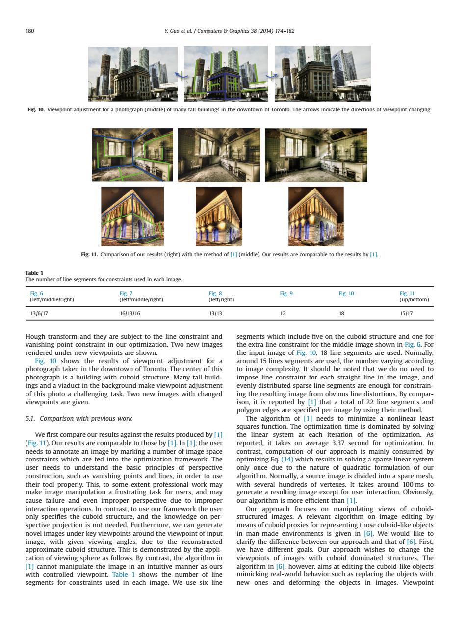
180 Y.Guo et al.Computers Graphics 38(2014)174-182 Fig.10.Viewpoint adjustment for a photograph(middle)of many tall buildings in the downtown of Toronto.The arrows indicate the directions of viewpoint changing. Fig.11.Comparison of our results(right)with the method of 1](middle).Our results are comparable to the results by 1. Table 1 The number of line segments for constraints used in each image. Fig.6 Fig.7 Fig.8 Fig.9 g.10 Fig.11 (left/middle/right) (left/middle/right) (left/right) (up/bottom) 13/6/17 16/13/16 13/13 12 18 15/17 Hough transform and they are subject to the line constraint and segments which include five on the cuboid structure and one for vanishing point constraint in our optimization.Two new images the extra line constraint for the middle image shown in Fig.6.For rendered under new viewpoints are shown. the input image of Fig.10,18 line segments are used.Normally Fig.10 shows the results of viewpoint adjustment for a around 15 lines segments are used,the number varying according photograph taken in the downtown of Toronto.The center of this to image complexity.It should be noted that we do no need to photograph is a building with cuboid structure.Many tall build- impose line constraint for each straight line in the image,and ings and a viaduct in the background make viewpoint adjustment evenly distributed sparse line segments are enough for constrain- of this photo a challenging task.Two new images with changed ing the resulting image from obvious line distortions.By compar- viewpoints are given. ison,it is reported by [1]that a total of 22 line segments and polygon edges are specified per image by using their method. 5.1.Comparison with previous work The algorithm of [1]needs to minimize a nonlinear least squares function.The optimization time is dominated by solving We first compare our results against the results produced by [1] the linear system at each iteration of the optimization.As (Fig.11).Our results are comparable to those by [11.In [11,the user reported,it takes on average 3.37 second for optimization.In needs to annotate an image by marking a number of image space contrast,computation of our approach is mainly consumed by constraints which are fed into the optimization framework.The optimizing Eq.(14)which results in solving a sparse linear system user needs to understand the basic principles of perspective only once due to the nature of quadratic formulation of our construction,such as vanishing points and lines,in order to use algorithm.Normally,a source image is divided into a spare mesh their tool properly.This,to some extent professional work may with several hundreds of vertexes.It takes around 100 ms to make image manipulation a frustrating task for users,and may generate a resulting image except for user interaction.Obviously. cause failure and even improper perspective due to improper our algorithm is more efficient than [1]. interaction operations.In contrast,to use our framework the user Our approach focuses on manipulating views of cuboid- only specifies the cuboid structure,and the knowledge on per- structured images.A relevant algorithm on image editing by spective projection is not needed.Furthermore,we can generate means of cuboid proxies for representing those cuboid-like objects novel images under key viewpoints around the viewpoint of input in man-made environments is given in [6].We would like to image,with given viewing angles,due to the reconstructed clarify the difference between our approach and that of [6.First, approximate cuboid structure.This is demonstrated by the appli- we have different goals.Our approach wishes to change the cation of viewing sphere as follows.By contrast,the algorithm in viewpoints of images with cuboid dominated structures.The [1]cannot manipulate the image in an intuitive manner as ours algorithm in 6].however,aims at editing the cuboid-like objects with controlled viewpoint.Table 1 shows the number of line mimicking real-world behavior such as replacing the objects with segments for constraints used in each image.We use six line new ones and deforming the objects in images.ViewpointHough transform and they are subject to the line constraint and vanishing point constraint in our optimization. Two new images rendered under new viewpoints are shown. Fig. 10 shows the results of viewpoint adjustment for a photograph taken in the downtown of Toronto. The center of this photograph is a building with cuboid structure. Many tall buildings and a viaduct in the background make viewpoint adjustment of this photo a challenging task. Two new images with changed viewpoints are given. 5.1. Comparison with previous work We first compare our results against the results produced by [1] (Fig. 11). Our results are comparable to those by [1]. In [1], the user needs to annotate an image by marking a number of image space constraints which are fed into the optimization framework. The user needs to understand the basic principles of perspective construction, such as vanishing points and lines, in order to use their tool properly. This, to some extent professional work may make image manipulation a frustrating task for users, and may cause failure and even improper perspective due to improper interaction operations. In contrast, to use our framework the user only specifies the cuboid structure, and the knowledge on perspective projection is not needed. Furthermore, we can generate novel images under key viewpoints around the viewpoint of input image, with given viewing angles, due to the reconstructed approximate cuboid structure. This is demonstrated by the application of viewing sphere as follows. By contrast, the algorithm in [1] cannot manipulate the image in an intuitive manner as ours with controlled viewpoint. Table 1 shows the number of line segments for constraints used in each image. We use six line segments which include five on the cuboid structure and one for the extra line constraint for the middle image shown in Fig. 6. For the input image of Fig. 10, 18 line segments are used. Normally, around 15 lines segments are used, the number varying according to image complexity. It should be noted that we do no need to impose line constraint for each straight line in the image, and evenly distributed sparse line segments are enough for constraining the resulting image from obvious line distortions. By comparison, it is reported by [1] that a total of 22 line segments and polygon edges are specified per image by using their method. The algorithm of [1] needs to minimize a nonlinear least squares function. The optimization time is dominated by solving the linear system at each iteration of the optimization. As reported, it takes on average 3.37 second for optimization. In contrast, computation of our approach is mainly consumed by optimizing Eq. (14) which results in solving a sparse linear system only once due to the nature of quadratic formulation of our algorithm. Normally, a source image is divided into a spare mesh, with several hundreds of vertexes. It takes around 100 ms to generate a resulting image except for user interaction. Obviously, our algorithm is more efficient than [1]. Our approach focuses on manipulating views of cuboidstructured images. A relevant algorithm on image editing by means of cuboid proxies for representing those cuboid-like objects in man-made environments is given in [6]. We would like to clarify the difference between our approach and that of [6]. First, we have different goals. Our approach wishes to change the viewpoints of images with cuboid dominated structures. The algorithm in [6], however, aims at editing the cuboid-like objects mimicking real-world behavior such as replacing the objects with new ones and deforming the objects in images. Viewpoint Fig. 10. Viewpoint adjustment for a photograph (middle) of many tall buildings in the downtown of Toronto. The arrows indicate the directions of viewpoint changing. Fig. 11. Comparison of our results (right) with the method of [1] (middle). Our results are comparable to the results by [1]. Table 1 The number of line segments for constraints used in each image. Fig. 6 (left/middle/right) Fig. 7 (left/middle/right) Fig. 8 (left/right) Fig. 9 Fig. 10 Fig. 11 (up/bottom) 13/6/17 16/13/16 13/13 12 18 15/17 180 Y. Guo et al. / Computers & Graphics 38 (2014) 174–182