正在加载图片...
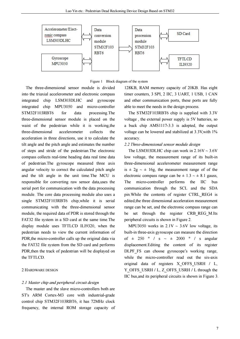
Luo Yin etc.:Pedestrian Dead Reckoning Device Design Based on STM32 Accelerometer Elect- Data Data ronic compass SDCard LSMB03DLHC STMB2F103 RBT6 RBT6 Gyroscope PU3050 9320 Figure 1 Block diagram of the systen The three-dimensional senso module is divided 128KB.RAM memory capacity of 20KB.Has eight into the triaxial accelerometer and electronic compass timer counters,3 SPL,2 IIC,3 UART,I USB,I CAM integrated chip LSM303DLHC and gyroscope and other communication ports.these ports are fully integrated chip MPU3050 and micro-controller able to meet the needs in the design process. STM32F103RBT6 for data processing.The The STM32F103RBT6 chip is supplied with 3.3V three-dimensional sensor module is placed on the the external p SV batteries,so waist of the pedestrian while it is working.the a buck chip AMS1117-3.3 is adopted,the outpu three-dimensional accelerometer collects the voltage can be lowered and stabilized at 3.3V,with 1% acceleration in three directions,use it to calculate the accuracy. tilt angle and the pitch angle and estimates the numbe 2.2 Three-dimensional sensor module design of steps and stride of the pedestr an. The LSM303DLHC chip can work in 2.16V~3.6V compcolcreal-tim re low voltage,the measurement range of its buil-ir of pedestrian.The gyroscope measured three axis three-dimensional accelerometer measurement range angular velocity to correct the calculated pitch angle is±2g~±16g.the measurement range ofof the and the tilt angle in the unit time.The MCU is electronic compass range can be 1.3 ~+8.1 gauss responsible for converting raw sensor datauses the The micro-controller performs the IIc bus through the SCL and the SDA module.The core data proces ing module also uses pin.While the contents of register CTRLREG4 is single STM32F103RBT6 chip.while it is seria edited the three dimensional acceleration measurement communicating with the three-dimensional senso range can be set.and the electronic compass range can module.the required data of PDR is stored through the be set through the register CRB REG M.Its FAT32 file system in a SD card at the same time.The s is shown in Figure 2 TFTLCD ILI9320.when the MPU3050 works in 2.1V 3.6V low voltage,its pedestrian needs to view the current information of built-in three-axis gyroscope can measure the direction PDR the micro-controller calls up the original data via of±250。/s~±2000。/s angular the FAT32 file system from the SD card and performs displacement.Editing the content of its register PDR,then the track of pedestrian will be displayed on DIPF FS can choosevscope'working range. theTFTLCD. while the micro-contoe r reac out the original data of registers X_OFFS_USRH L 2 HARDWARE DESIGN Y OFFS USRH/L.Z OFFS USRH/L through the IIC bus,and its peripheral circuits is shown in Figure 3. 2.1 Master chip and peripheral circuit design The maste and the slave botha STs ARM Cortex-M3 core with industrial-grade control chip STM32F103RBT6,it has 72MHz clock frequency,the internal ROM storage capacity ofLuo Yin etc.: Pedestrian Dead Reckoning Device Design Based on STM32 7 Figure 1 Block diagram of the system The three-dimensional sensor module is divided into the triaxial accelerometer and electronic compass integrated chip LSM303DLHC and gyroscope integrated chip MPU3050 and micro-controller STM32F103RBT6 for data processing.The three-dimensional sensor module is placed on the waist of the pedestrian while it is working,the three-dimensional accelerometer collects the acceleration in three directions, use it to calculate the tilt angle and the pitch angle and estimates the number of steps and stride of the pedestrian.The electronic compass collects real-time heading data real time data of pedestrian.The gyroscope measured three axis angular velocity to correct the calculated pitch angle and the tilt angle in the unit time.The MCU is responsible for converting raw sensor data,uses the serial port for communication with the data processing module. The core data processing module also uses a single STM32F103RBT6 chip,while it is serial communicating with the three-dimensional sensor module, the required data of PDR is stored through the FAT32 file system in a SD card at the same time.The display module uses TFTLCD ILI9320, when the pedestrian needs to view the current information of PDR,the micro-controller calls up the original data via the FAT32 file system from the SD card and performs PDR,then the track of pedestrian will be displayed on the TFTLCD. 2 HARDWARE DESIGN 2.1 Master chip and peripheral circuit design The master and the slave micro-controllers both are ST's ARM Cortex-M3 core with industrial-grade control chip STM32F103RBT6, it has 72MHz clock frequency, the internal ROM storage capacity of 128KB, RAM memory capacity of 20KB. Has eight timer counters, 3 SPI, 2 IIC, 3 UART, 1 USB, 1 CAN and other communication ports, these ports are fully able to meet the needs in the design process. The STM32F103RBT6 chip is supplied with 3.3V voltage , the external power supply is 5V batteries, so a buck chip AMS1117-3.3 is adopted, the output voltage can be lowered and stabilized at 3.3V,with 1% accuracy. 2.2 Three-dimensional sensor module design The LSM303DLHC chip can work in 2.16V ~ 3.6V low voltage, the measurement range of its built-in three-dimensional accelerometer measurement range is ± 2g ~ ± 16g, the measurement range of of the electronic compass range can be ± 1.3 ~ ± 8.1 gauss, The micro-controller performs the IIC bus communication through the SCL and the SDA pin.While the contents of register CTRL_REG4 is edited,the three dimensional acceleration measurement range can be set, and the electronic compass range can be set through the register CRB_REG_M.Its peripheral circuits is shown in Figure 2. MPU3050 works in 2.1V ~ 3.6V low voltage, its built-in three-axis gyroscope can measure the direction of ± 250 ° / s ~ ± 2000 ° / s angular displacement.Editing the content of its register DLPF_FS can choose gyroscope’s working range, while the micro-controller read out the six-axis original data of registers X_OFFS_USRH / L, Y_OFFS_USRH / L, Z_OFFS_USRH / L through the IIC bus,and its peripheral circuits is shown in Figure 3