正在加载图片...
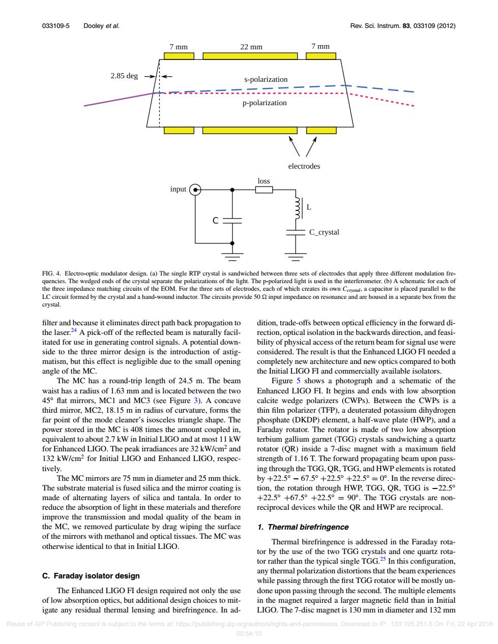
033109-5 Dooley et al. Rev.Sci.Instrum.83,033109(2012) 7 mm 22 mm 2.85 deg s-polarization p-polarization electrodes loss input(● C crystal FIG.4.Electro-optic modulator design.(a)The single RTP crystal is sandwiched between three sets of electrodes that apply three different modulation fre- quencies.The wedged ends of the crystal separate the polarizations of the light.The p-polarized light is used in the interferometer.(b)A schematic for each of the three impedance matching circuits of the EOM.For the three sets of electrodes,each of which creates its own C a capacitor is placed parallel to the LC circuit formed by the crystal and a hand-wound inductor.The circuits provide 50 input impedance on resonance and are housed in a separate box from the crystal. filter and because it eliminates direct path back propagation to dition,trade-offs between optical efficiency in the forward di- the laser.24 A pick-off of the reflected beam is naturally facil- rection,optical isolation in the backwards direction,and feasi- itated for use in generating control signals.A potential down- bility of physical access of the return beam for signal use were side to the three mirror design is the introduction of astig- considered.The result is that the Enhanced LIGO FI needed a matism,but this effect is negligible due to the small opening completely new architecture and new optics compared to both angle of the MC. the Initial LIGO FI and commercially available isolators. The MC has a round-trip length of 24.5 m.The beam Figure 5 shows a photograph and a schematic of the waist has a radius of 1.63 mm and is located between the two Enhanced LIGO FI.It begins and ends with low absorption 45 flat mirrors,MC1 and MC3(see Figure 3).A concave calcite wedge polarizers (CWPs).Between the CWPs is a third mirror,MC2,18.15 m in radius of curvature,forms the thin film polarizer(TFP),a deuterated potassium dihydrogen far point of the mode cleaner's isosceles triangle shape.The phosphate (DKDP)element,a half-wave plate (HWP),and a power stored in the MC is 408 times the amount coupled in, Faraday rotator.The rotator is made of two low absorption equivalent to about 2.7 kW in Initial LIGO and at most 11 kW terbium gallium garnet(TGG)crystals sandwiching a quartz for Enhanced LIGO.The peak irradiances are 32 kW/cm2 and rotator(QR)inside a 7-disc magnet with a maximum field 132 kW/cm2 for Initial LIGO and Enhanced LIGO,respec- strength of 1.16 T.The forward propagating beam upon pass- tively. ing through the TGG,QR,TGG,and HWP elements is rotated The MC mirrors are 75 mm in diameter and 25 mm thick. by+22.5°-67.5°+22.5°+22.5°=0°.n the reverse direc-. The substrate material is fused silica and the mirror coating is tion,the rotation through HWP,TGG,QR,TGG is -22.5 made of alternating layers of silica and tantala.In order to +22.5°+67.5°+22.5°=90°.The TGG crystals are non-- reduce the absorption of light in these materials and therefore reciprocal devices while the QR and HWP are reciprocal. improve the transmission and modal quality of the beam in the MC,we removed particulate by drag wiping the surface 1.Thermal birefringence of the mirrors with methanol and optical tissues.The MC was otherwise identical to that in Initial LIGO. Thermal birefringence is addressed in the Faraday rota- tor by the use of the two TGG crystals and one quartz rota- tor rather than the typical single TGG.25 In this configuration, any thermal polarization distortions that the beam experiences C.Faraday isolator design while passing through the first TGG rotator will be mostly un- The Enhanced LIGO FI design required not only the use done upon passing through the second.The multiple elements of low absorption optics,but additional design choices to mit- in the magnet required a larger magnetic field than in Initial igate any residual thermal lensing and birefringence.In ad- LIGO.The 7-disc magnet is 130 mm in diameter and 132 mm Reuse of AlP Publishing content is subject to the terms at:https://publishing.aip.org/authors/rights-and-permissions.Download to IP:183.195.251.6 On:Fri.22 Apr 2016 00:54:10033109-5 Dooley et al. Rev. Sci. Instrum. 83, 033109 (2012) FIG. 4. Electro-optic modulator design. (a) The single RTP crystal is sandwiched between three sets of electrodes that apply three different modulation frequencies. The wedged ends of the crystal separate the polarizations of the light. The p-polarized light is used in the interferometer. (b) A schematic for each of the three impedance matching circuits of the EOM. For the three sets of electrodes, each of which creates its own Ccrystal, a capacitor is placed parallel to the LC circuit formed by the crystal and a hand-wound inductor. The circuits provide 50 input impedance on resonance and are housed in a separate box from the crystal. filter and because it eliminates direct path back propagation to the laser.24 A pick-off of the reflected beam is naturally facilitated for use in generating control signals. A potential downside to the three mirror design is the introduction of astigmatism, but this effect is negligible due to the small opening angle of the MC. The MC has a round-trip length of 24.5 m. The beam waist has a radius of 1.63 mm and is located between the two 45◦ flat mirrors, MC1 and MC3 (see Figure 3). A concave third mirror, MC2, 18.15 m in radius of curvature, forms the far point of the mode cleaner’s isosceles triangle shape. The power stored in the MC is 408 times the amount coupled in, equivalent to about 2.7 kW in Initial LIGO and at most 11 kW for Enhanced LIGO. The peak irradiances are 32 kW/cm2 and 132 kW/cm2 for Initial LIGO and Enhanced LIGO, respectively. The MC mirrors are 75 mm in diameter and 25 mm thick. The substrate material is fused silica and the mirror coating is made of alternating layers of silica and tantala. In order to reduce the absorption of light in these materials and therefore improve the transmission and modal quality of the beam in the MC, we removed particulate by drag wiping the surface of the mirrors with methanol and optical tissues. The MC was otherwise identical to that in Initial LIGO. C. Faraday isolator design The Enhanced LIGO FI design required not only the use of low absorption optics, but additional design choices to mitigate any residual thermal lensing and birefringence. In addition, trade-offs between optical efficiency in the forward direction, optical isolation in the backwards direction, and feasibility of physical access of the return beam for signal use were considered. The result is that the Enhanced LIGO FI needed a completely new architecture and new optics compared to both the Initial LIGO FI and commercially available isolators. Figure 5 shows a photograph and a schematic of the Enhanced LIGO FI. It begins and ends with low absorption calcite wedge polarizers (CWPs). Between the CWPs is a thin film polarizer (TFP), a deuterated potassium dihydrogen phosphate (DKDP) element, a half-wave plate (HWP), and a Faraday rotator. The rotator is made of two low absorption terbium gallium garnet (TGG) crystals sandwiching a quartz rotator (QR) inside a 7-disc magnet with a maximum field strength of 1.16 T. The forward propagating beam upon passing through the TGG, QR, TGG, and HWP elements is rotated by +22.5◦ − 67.5◦ +22.5◦ +22.5◦ = 0◦. In the reverse direction, the rotation through HWP, TGG, QR, TGG is −22.5◦ +22.5◦ +67.5◦ +22.5◦ = 90◦. The TGG crystals are nonreciprocal devices while the QR and HWP are reciprocal. 1. Thermal birefringence Thermal birefringence is addressed in the Faraday rotator by the use of the two TGG crystals and one quartz rotator rather than the typical single TGG.25 In this configuration, any thermal polarization distortions that the beam experiences while passing through the first TGG rotator will be mostly undone upon passing through the second. The multiple elements in the magnet required a larger magnetic field than in Initial LIGO. The 7-disc magnet is 130 mm in diameter and 132 mm Reuse of AIP Publishing content is subject to the terms at: https://publishing.aip.org/authors/rights-and-permissions. Download to IP: 183.195.251.6 On: Fri, 22 Apr 2016 00:54:10