正在加载图片...
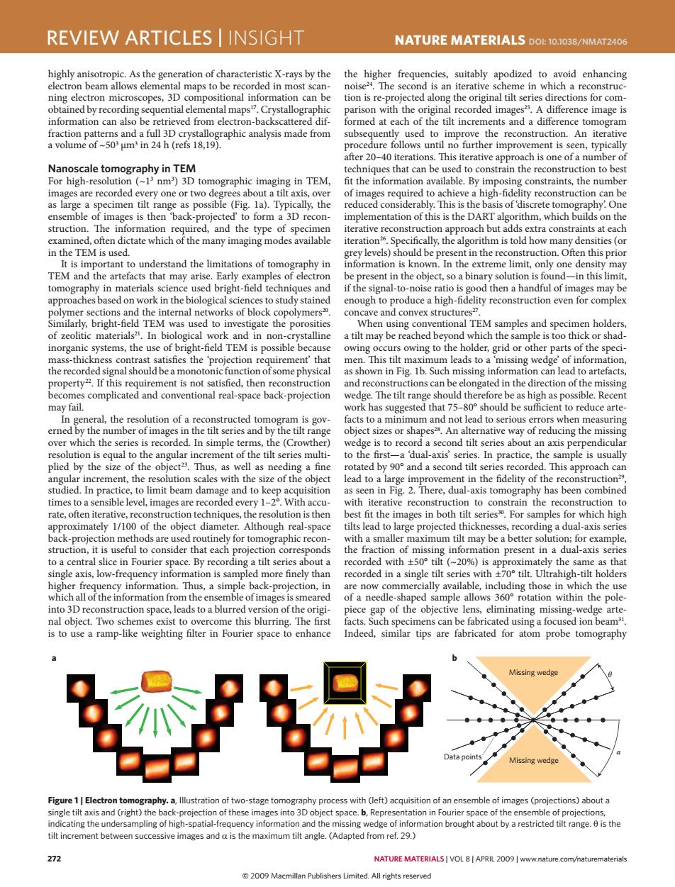
REVIEW ARTICLES INSIGHT NATURE MATERIALS DOL:10.1038/NMAT2406 highly anisotropic.As the generation of characteristic X-rays by the the higher frequencies,suitably apodized to avoid enhancing electron beam allows elemental maps to be recorded in most scan- noise2.The second is an iterative scheme in which a reconstruc- ning electron microscopes,3D compositional information can be tion is re-projected along the original tilt series directions for com- obtained by recording sequential elemental maps.Crystallographic parison with the original recorded images25.A difference image is information can also be retrieved from electron-backscattered dif- formed at each of the tilt increments and a difference tomogram fraction patterns and a full 3D crystallographic analysis made from subsequently used to improve the reconstruction.An iterative a volume of~503 um3 in 24 h (refs 18,19). procedure follows until no further improvement is seen,typically after 20-40 iterations.This iterative approach is one of a number of Nanoscale tomography in TEM techniques that can be used to constrain the reconstruction to best For high-resolution (~13 nm)3D tomographic imaging in TEM, fit the information available.By imposing constraints,the number images are recorded every one or two degrees about a tilt axis,over of images required to achieve a high-fidelity reconstruction can be as large a specimen tilt range as possible (Fig.1a).Typically,the reduced considerably.This is the basis of 'discrete tomography.One ensemble of images is then 'back-projected'to form a 3D recon- implementation of this is the DART algorithm,which builds on the struction.The information required,and the type of specimen iterative reconstruction approach but adds extra constraints at each examined,often dictate which of the many imaging modes available iteration2.Specifically,the algorithm is told how many densities (or in the TEM is used. grey levels)should be present in the reconstruction.Often this prior It is important to understand the limitations of tomography in information is known.In the extreme limit,only one density may TEM and the artefacts that may arise.Early examples of electron be present in the object,so a binary solution is found-in this limit, tomography in materials science used bright-field techniques and if the signal-to-noise ratio is good then a handful of images may be approaches based on work in the biological sciences to study stained enough to produce a high-fidelity reconstruction even for complex polymer sections and the internal networks of block copolymers2. concave and convex structures?. Similarly,bright-field TEM was used to investigate the porosities When using conventional TEM samples and specimen holders, of zeolitic materials".In biological work and in non-crystalline a tilt may be reached beyond which the sample is too thick or shad- inorganic systems,the use of bright-field TEM is possible because owing occurs owing to the holder,grid or other parts of the speci- mass-thickness contrast satisfies the 'projection requirement'that men.This tilt maximum leads to a 'missing wedge'of information, the recorded signal should be a monotonic function of some physical as shown in Fig.1b.Such missing information can lead to artefacts, property22.If this requirement is not satisfied,then reconstruction and reconstructions can be elongated in the direction of the missing becomes complicated and conventional real-space back-projection wedge.The tilt range should therefore be as high as possible.Recent may fail. work has suggested that 75-80 should be sufficient to reduce arte- In general,the resolution of a reconstructed tomogram is gov- facts to a minimum and not lead to serious errors when measuring erned by the number of images in the tilt series and by the tilt range object sizes or shapes28.An alternative way of reducing the missing over which the series is recorded.In simple terms,the (Crowther) wedge is to record a second tilt series about an axis perpendicular resolution is equal to the angular increment of the tilt series multi- to the first-a 'dual-axis'series.In practice,the sample is usually plied by the size of the object2.Thus,as well as needing a fine rotated by 90 and a second tilt series recorded.This approach can angular increment,the resolution scales with the size of the object lead to a large improvement in the fidelity of the reconstruction2, studied.In practice,to limit beam damage and to keep acquisition as seen in Fig.2.There,dual-axis tomography has been combined times to a sensible level,images are recorded every 1-2.With accu- with iterative reconstruction to constrain the reconstruction to rate,often iterative,reconstruction techniques,the resolution is then best fit the images in both tilt series%.For samples for which high approximately 1/100 of the object diameter.Although real-space tilts lead to large projected thicknesses,recording a dual-axis series back-projection methods are used routinely for tomographic recon- with a smaller maximum tilt may be a better solution;for example, struction,it is useful to consider that each projection corresponds the fraction of missing information present in a dual-axis series to a central slice in Fourier space.By recording a tilt series about a recorded with +50 tilt(~20%)is approximately the same as that single axis,low-frequency information is sampled more finely than recorded in a single tilt series with +70 tilt.Ultrahigh-tilt holders higher frequency information.Thus,a simple back-projection,in are now commercially available,including those in which the use which all of the information from the ensemble of images is smeared of a needle-shaped sample allows 360 rotation within the pole- into 3D reconstruction space,leads to a blurred version of the origi- piece gap of the objective lens,eliminating missing-wedge arte- nal object.Two schemes exist to overcome this blurring.The first facts.Such specimens can be fabricated using a focused ion beam" is to use a ramp-like weighting filter in Fourier space to enhance Indeed,similar tips are fabricated for atom probe tomography Missing wedge ata points Missing wedge Figure 1 Electron tomography.a,Illustration of two-stage tomography process with (left)acquisition of an ensemble of images (projections)about a single tilt axis and(right)the back-projection of these images into 3D object space.b,Representation in Fourier space of the ensemble of projections, indicating the undersampling of high-spatial-frequency information and the missing wedge of information brought about by a restricted tilt range.0 is the tilt increment between successive images and a is the maximum tilt angle.(Adapted from ref.29.) 272 NATURE MATERIALS VOL 8 APRIL 2009|www.nature.com/naturematerials 2009 Macmillan Publishers Limited.All rights reserved272 nature materials | VOL 8 | APRIL 2009 | www.nature.com/naturematerials review articles | insight NaTure maTerIals doi: 10.1038/nmat2406 highly anisotropic. As the generation of characteristic X-rays by the electron beam allows elemental maps to be recorded in most scanning electron microscopes, 3D compositional information can be obtained by recording sequential elemental maps17. Crystallographic information can also be retrieved from electron-backscattered diffraction patterns and a full 3D crystallographic analysis made from a volume of ~503 μm3 in 24 h (refs 18,19). nanoscale tomography in tem For high-resolution (~13 nm3 ) 3D tomographic imaging in TEM, images are recorded every one or two degrees about a tilt axis, over as large a specimen tilt range as possible (Fig. 1a). Typically, the ensemble of images is then ‘back-projected’ to form a 3D reconstruction. The information required, and the type of specimen examined, often dictate which of the many imaging modes available in the TEM is used. It is important to understand the limitations of tomography in TEM and the artefacts that may arise. Early examples of electron tomography in materials science used bright-field techniques and approaches based on work in the biological sciences to study stained polymer sections and the internal networks of block copolymers20. Similarly, bright-field TEM was used to investigate the porosities of zeolitic materials21. In biological work and in non-crystalline inorganic systems, the use of bright-field TEM is possible because mass-thickness contrast satisfies the ‘projection requirement’ that the recorded signal should be a monotonic function of some physical property22. If this requirement is not satisfied, then reconstruction becomes complicated and conventional real-space back-projection may fail. In general, the resolution of a reconstructed tomogram is governed by the number of images in the tilt series and by the tilt range over which the series is recorded. In simple terms, the (Crowther) resolution is equal to the angular increment of the tilt series multiplied by the size of the object23. Thus, as well as needing a fine angular increment, the resolution scales with the size of the object studied. In practice, to limit beam damage and to keep acquisition times to a sensible level, images are recorded every 1–2°. With accurate, often iterative, reconstruction techniques, the resolution is then approximately 1/100 of the object diameter. Although real-space back-projection methods are used routinely for tomographic reconstruction, it is useful to consider that each projection corresponds to a central slice in Fourier space. By recording a tilt series about a single axis, low-frequency information is sampled more finely than higher frequency information. Thus, a simple back-projection, in which all of the information from the ensemble of images is smeared into 3D reconstruction space, leads to a blurred version of the original object. Two schemes exist to overcome this blurring. The first is to use a ramp-like weighting filter in Fourier space to enhance the higher frequencies, suitably apodized to avoid enhancing noise24. The second is an iterative scheme in which a reconstruction is re-projected along the original tilt series directions for comparison with the original recorded images25. A difference image is formed at each of the tilt increments and a difference tomogram subsequently used to improve the reconstruction. An iterative procedure follows until no further improvement is seen, typically after 20–40 iterations. This iterative approach is one of a number of techniques that can be used to constrain the reconstruction to best fit the information available. By imposing constraints, the number of images required to achieve a high-fidelity reconstruction can be reduced considerably. This is the basis of ‘discrete tomography’. One implementation of this is the DART algorithm, which builds on the iterative reconstruction approach but adds extra constraints at each iteration26. Specifically, the algorithm is told how many densities (or grey levels) should be present in the reconstruction. Often this prior information is known. In the extreme limit, only one density may be present in the object, so a binary solution is found—in this limit, if the signal-to-noise ratio is good then a handful of images may be enough to produce a high-fidelity reconstruction even for complex concave and convex structures27. When using conventional TEM samples and specimen holders, a tilt may be reached beyond which the sample is too thick or shadowing occurs owing to the holder, grid or other parts of the specimen. This tilt maximum leads to a ‘missing wedge’ of information, as shown in Fig. 1b. Such missing information can lead to artefacts, and reconstructions can be elongated in the direction of the missing wedge. The tilt range should therefore be as high as possible. Recent work has suggested that 75–80° should be sufficient to reduce artefacts to a minimum and not lead to serious errors when measuring object sizes or shapes28. An alternative way of reducing the missing wedge is to record a second tilt series about an axis perpendicular to the first—a ‘dual-axis’ series. In practice, the sample is usually rotated by 90° and a second tilt series recorded. This approach can lead to a large improvement in the fidelity of the reconstruction29, as seen in Fig. 2. There, dual-axis tomography has been combined with iterative reconstruction to constrain the reconstruction to best fit the images in both tilt series30. For samples for which high tilts lead to large projected thicknesses, recording a dual-axis series with a smaller maximum tilt may be a better solution; for example, the fraction of missing information present in a dual-axis series recorded with ±50° tilt (~20%) is approximately the same as that recorded in a single tilt series with ±70° tilt. Ultrahigh-tilt holders are now commercially available, including those in which the use of a needle-shaped sample allows 360° rotation within the polepiece gap of the objective lens, eliminating missing-wedge artefacts. Such specimens can be fabricated using a focused ion beam31. Indeed, similar tips are fabricated for atom probe tomography a b Data points Missing wedge Missing wedge θ α Figure 1 | electron tomography. a, Illustration of two-stage tomography process with (left) acquisition of an ensemble of images (projections) about a single tilt axis and (right) the back-projection of these images into 3D object space. b, Representation in Fourier space of the ensemble of projections, indicating the undersampling of high-spatial-frequency information and the missing wedge of information brought about by a restricted tilt range. θ is the tilt increment between successive images and α is the maximum tilt angle. (Adapted from ref. 29.) nmat_2406_APR09.indd 272 13/3/09 12:08:30 © 2009 Macmillan Publishers Limited. All rights reserved