正在加载图片...
This article has been accepted for publication in a future issue of this journal,but has not been fully edited Content may change prior to final publication.Citation information:DOI 10.1109/TMC.2018.2857812.IEEE Transactions on Mobile Computing pair,i.e.,di>d and d2>d,suppose that the angle of 00 arrival of the tagged objects is a,then Candidale Solution of (A,】 Candidale Solution of (AA Candidate Solution of (A △d=d1-d2=dcosa. (4) Cardidse Salution of (A A didate Solution of (A Furthermore,when the distance between the antenna pair is l (A.A less than half of the wavelength,i.e.,d <we can figure 150 ◆Real Position(-80,1B0) out a pair of symmetric solutions for the angle of arrival 100 of the tagged object.In this regard,we can further use the phase difference between the two antennas to depict the A2 value of△d,i.e,△d=ld1-d2l=△0=l91-f2l.Therefore, 5 we can figure out the angle of arrival of the tagged objects The horncoordinate(cm) using the equation: Fig.8.Figure out the unique solution of the tag's position △8 a arccos( (5) 5.2.4 Deriving the angle-distance pair After deriving the target tag's position,we can further de- As a matter of fact,by leveraging the method of angle of rive the angle when the tag is at the perpendicular point of the arrival at antenna pair,we are able to use the asymptotic lines RFID antennas,that is the moment when the perpendicular of the hyperbolas to approximate the candidate position of the bisector of the midpoint of the antenna pairs crosses the tagged object,as long as the tagged object is relatively far tag.We use the pair(0,6)to denote this situation,here from the antenna pair. denotes the offset angle of the antenna,and 6 denotes the RFID Tag vertical distance.The pair (0,6)is computed as follows: 0=arctan号,and6=√r2+y2.Therefore,we can further leverage an algorithm like Algorithm 2 to match multiple tags to multiple objects d1 d2 Algorithm 1 Match multiple objects to multiple tags d1-d2=01-e2=dcosa 1:Extract the vector:After continuous scanning,identify Antenna Paird the peak value from the depth curve and the crossing point of multiple hyperbolas derived from phase pairs. A1 A2 For each object Oi,label it with a vector (0i,di),respec- Fig.7.Angle of arrival at antenna pair tively normalize the angle and depth into the interval Fig.8 shows an example of deriving the unique solution [0,1]by dividing the maximum value of angle and of tag's position from the intersections.Suppose a target tag is deployed at the coordinate (-60,180).We first ob- depth,and add the vector to a set O;For each tag Tj, tain the phase values(2.58,5.81)from the two antennas label it with a vector(0j,6),normalize it and add the when they are respectively at the position of A1 and A2. vector to a set T. 2:while O≠0orT≠odo After the antenna pair is rotated with a degree of 40, Match the objects and tags:For each object O;EO we then obtain the phase values (5.56,2.49)from the two antennas when they are respectively at the position of A with vector(0i,di),compute the distance with each tagT,∈T with vector(g,d〉as follows: and A3.In this way,we can obtain three pairs of phase values(2.58,5.81),(2.58,5.56),and(5.81,2.49),which are △=V0:-,)2+(d-6)2 respectively collected from antenna pairs(A1,A2),(A1,A1), and(A2,A2).We can respectively use them to compute the Select the tag Ti with the minimum distance and pair feasible solutions in a unified coordinate system.We use the object O:with the tag Tjt. different colors to label the hyperbolas of multiple feasible 4: Calibrate the matching results:For any tag T;E T solutions according to different pairs of phase values.By us- paired with multiple objects,select the object O;from ing the method of angle of arrival,we use the asymptotic lines these objects with the minimum distance Ai.i,and to approximate the corresponding hyperbolas.For example, pair the object Oi with the tag Ti.Respectively re- as the distance between A1 and A2 is greater than half the move the object O:and the tag T from set O and wave length,two pairs of symmetric directions of the tagged T object are derived,marked with red color;as the distance 5:end while between A and A is less than half the wave length,one 6:Output the matched pairs of objects and tags. pair of symmetric directions of the tagged object are derived, marked with blue color;similarly,as the distance between 5.3 Tackle the Issues of Interferences A2 and A is less than half the wave length,one pair of symmetric directions of the tagged object are derived, 5.3.1 Impact of Interferences marked with black color.Moreover,the multiple hyperbolas Due to the environmental issues like the multi-path fading of different feasible solutions all intersect at a small area and object occlusion,the system may fail to identify some of which is very close to the target tag's real position.We thus the objects and the tags.For example,the multi-path fading set the central point of the intersection region as the estimate may cause the line-of-sight RF-signal and the reflected RF- value of the tag's position. signals to offset each other at the tag's position,such that 1536-1233(c)2018 IEEE Personal use is permitted,but republication/redistribution requires IEEE permission.See http://www.ieee.org/publications_standards/publications/rights/index.html for more information.1536-1233 (c) 2018 IEEE. Personal use is permitted, but republication/redistribution requires IEEE permission. See http://www.ieee.org/publications_standards/publications/rights/index.html for more information. This article has been accepted for publication in a future issue of this journal, but has not been fully edited. Content may change prior to final publication. Citation information: DOI 10.1109/TMC.2018.2857812, IEEE Transactions on Mobile Computing 7 pair, i.e., d1
d and d2
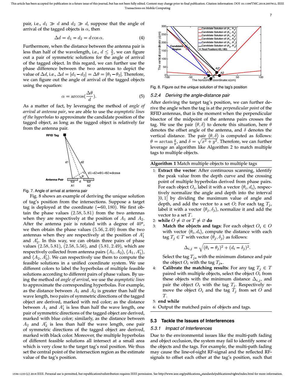
d, suppose that the angle of arrival of the tagged objects is α, then ∆d = d1 − d2 = d cos α. (4) Furthermore, when the distance between the antenna pair is less than half of the wavelength, i.e., d ≤ λ 2 , we can figure out a pair of symmetric solutions for the angle of arrival of the tagged object. In this regard, we can further use the phase difference between the two antennas to depict the value of ∆d, i.e., ∆d = |d1−d2| = ∆θ = |θ1−θ2|. Therefore, we can figure out the angle of arrival of the tagged objects using the equation: α = arccos(∆θ d ). (5) As a matter of fact, by leveraging the method of angle of arrival at antenna pair, we are able to use the asymptotic lines of the hyperbolas to approximate the candidate position of the tagged object, as long as the tagged object is relatively far from the antenna pair. d1-d2=&1-&2=dcosα α A1 A2 d1 d2 d Antenna Pair RFID Tag Fig. 7. Angle of arrival at antenna pair Fig. 8 shows an example of deriving the unique solution of tag’s position from the intersections. Suppose a target tag is deployed at the coordinate (−60, 180). We first obtain the phase values (2.58, 5.81) from the two antennas when they are respectively at the position of A1 and A2. After the antenna pair is rotated with a degree of 40◦ , we then obtain the phase values (5.56, 2.49) from the two antennas when they are respectively at the position of A0 1 and A0 2 . In this way, we can obtain three pairs of phase values (2.58, 5.81), (2.58, 5.56), and (5.81, 2.49), which are respectively collected from antenna pairs hA1, A2i, hA1, A0 1 i, and hA2, A0 2 i. We can respectively use them to compute the feasible solutions in a unified coordinate system. We use different colors to label the hyperbolas of multiple feasible solutions according to different pairs of phase values. By using the method of angle of arrival, we use the asymptotic lines to approximate the corresponding hyperbolas. For example, as the distance between A1 and A2 is greater than half the wave length, two pairs of symmetric directions of the tagged object are derived, marked with red color; as the distance between A1 and A0 1 is less than half the wave length, one pair of symmetric directions of the tagged object are derived, marked with blue color; similarly, as the distance between A2 and A0 2 is less than half the wave length, one pair of symmetric directions of the tagged object are derived, marked with black color. Moreover, the multiple hyperbolas of different feasible solutions all intersect at a small area which is very close to the target tag’s real position. We thus set the central point of the intersection region as the estimate value of the tag’s position. The horizontal coordinate:x(cm) -100 -50 0 50 100 The vertical coordinate:y(cm) 0 50 100 150 200 250 300 Candidate Solution of (A1 , A2 ) Candidate Solution of (A1 , A2 ) Candidate Solution of (A1 , A2 ) Candidate Solution of (A1 , A2 ) Candidate Solution of (A1 , A'1 ) Candidate Solution of (A2 , A'2 ) Real Position(-60,180) Candidate Region A1 A2 A1’ A2’ Fig. 8. Figure out the unique solution of the tag’s position 5.2.4 Deriving the angle-distance pair After deriving the target tag’s position, we can further derive the angle when the tag is at the perpendicular point of the RFID antennas, that is the moment when the perpendicular bisector of the midpoint of the antenna pairs crosses the tag. We use the pair hθ, δi to denote this situation, here θ denotes the offset angle of the antenna, and δ denotes the vertical distance. The pair hθ, δi is computed as follows: θ = arctan x y , and δ = p x 2 + y 2. Therefore, we can further leverage an algorithm like Algorithm 2 to match multiple tags to multiple objects. Algorithm 1 Match multiple objects to multiple tags 1: Extract the vector: After continuous scanning, identify the peak value from the depth curve and the crossing point of multiple hyperbolas derived from phase pairs. For each object Oi , label it with a vector hθi , dii, respectively normalize the angle and depth into the interval [0, 1] by dividing the maximum value of angle and depth, and add the vector to a set O; For each tag Tj , label it with a vector hθj , δj i, normalize it and add the vector to a set T. 2: while O 6= ∅ or T 6= ∅ do 3: Match the objects and tags: For each object Oi ∈ O with vector hθi , dii, compute the distance with each tag Tj ∈ T with vector hθj , δj i as follows: ∆i,j = q (θi − θj ) 2 + (di − δj ) 2. Select the tag Tj∗ with the minimum distance and pair the object Oi with the tag Tj∗. 4: Calibrate the matching results: For any tag Tj ∈ T paired with multiple objects, select the object Oi from these objects with the minimum distance ∆i,j , and pair the object Oi with the tag Tj . Respectively remove the object Oi and the tag Tj from set O and T. 5: end while 6: Output the matched pairs of objects and tags. 5.3 Tackle the Issues of Interferences 5.3.1 Impact of Interferences Due to the environmental issues like the multi-path fading and object occlusion, the system may fail to identify some of the objects and the tags. For example, the multi-path fading may cause the line-of-sight RF-signal and the reflected RFsignals to offset each other at the tag’s position, such that