正在加载图片...
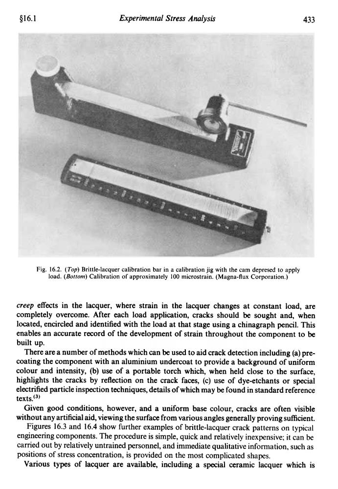
s16.1 Experimental Stress Analysis 433 Fig.16.2.(Top)Brittle-lacquer calibration bar in a calibration jig with the cam depresed to apply load.(Bottom)Calibration of approximately 100 microstrain.(Magna-flux Corporation.) creep effects in the lacquer,where strain in the lacquer changes at constant load,are completely overcome.After each load application,cracks should be sought and,when located,encircled and identified with the load at that stage using a chinagraph pencil.This enables an accurate record of the development of strain throughout the component to be built up. There are a number of methods which can be used to aid crack detection including(a)pre- coating the component with an aluminium undercoat to provide a background of uniform colour and intensity,(b)use of a portable torch which,when held close to the surface, highlights the cracks by reflection on the crack faces,(c)use of dye-etchants or special electrified particle inspection techniques,details of which may be found in standard reference texts.(3) Given good conditions,however,and a uniform base colour,cracks are often visible without any artificial aid,viewing the surface from various angles generally proving sufficient. Figures 16.3 and 16.4 show further examples of brittle-lacquer crack patterns on typical engineering components.The procedure is simple,quick and relatively inexpensive;it can be carried out by relatively untrained personnel,and immediate qualitative information,such as positions of stress concentration,is provided on the most complicated shapes. Various types of lacquer are available,including a special ceramic lacquer which is§16.1 Experimental Stress Analysis 433 Fig. 16.2. (Top) Brittle-lacquer calibration bar in a calibration jig with the cam depresed to apply load. (Bollom) Calibration of approximately 100 microstrain. (Magna-flux Corporation.) creep effects in the lacquer, where strain in the lacquer changes at constant load, are completely overcome. After each load application, cracks should be sought and, when located, encircled and identified with the load at that stage using a chinagraph pencil. This enables an accurate record of the development of strain throughout the component to be built up. There are a number of methods which can be used to aid crack detection including (a) precoating the component with an aluminium undercoat to provide a background of uniform colour and intensity, (b) use of a portable torch which, when held close to the surface, highlights the cracks by reflection on the crack faces, (c) use of dye-etchants or special electrified particle inspection techniques, details of which may be found in standard reference texts.<3) Given good conditions, however, and a uniform base colour, cracks are often visible without any artificial aid, viewing the surface from various angles generally proving sufficient. Figures 16.3 and 16.4 show further examples of brittle-lacquer crack patterns on typical engineering components. The procedure is simple, quick and relatively inexpensive; it can be carried out by relatively untrained personnel, and immediate qualitative information, such as positions of stress concentration, is provided on the most complicated shapes. Various types of lacquer are available, including a special ceramic lacquer which is