正在加载图片...
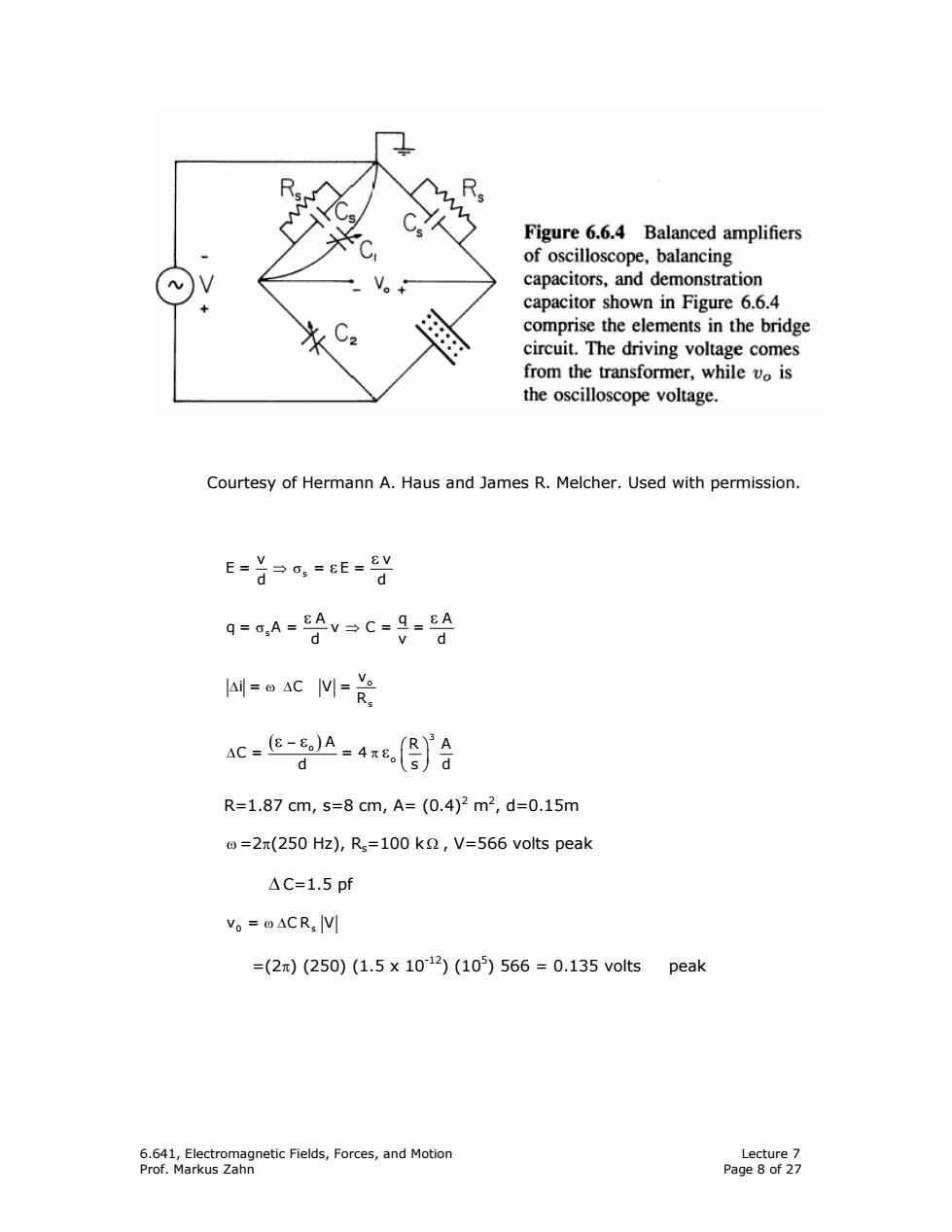
Figure 6.6.4 Balanced amplifiers of oscilloscope,balancing capacitors,and demonstration capacitor shown in Figure 6.6.4 8 comprise the elements in the bridge circuit.The driving voltage comes from the transformer,while vo is the oscilloscope voltage. Courtesy of Hermann A.Haus and James R.Melcher.Used with permission. E=首p,=eE=y d q=o,A=8Av→C=9=8A d d AC M sc.e-g.4合 d R=1.87cm,s=8cm,A=(0.4)2m2,d=0.15m @=2(250 Hz),Rs=100 k,V=566 volts peak △C=1.5pf V。=oACR,V =(2π)(250)(1.5×10¹²)(105)566=0.135 volts peak 6.641,Electromagnetic Fields,Forces,and Motion Lecture 7 Prof.Markus Zahn Page 8 of 276.641, Electromagnetic Fields, Forces, and Motion Lecture 7 Prof. Markus Zahn Page 8 of 27 Courtesy of Hermann A. Haus and James R. Melcher. Used with permission. s v v E= = E= d d ⇒ σ ε ε s A qA q= A= v C= = d vd σ ⇒ ε ε ∆ ω∆ o s v i= C V= R ( − ) ⎛ ⎞ ∆ π ⎜ ⎟ ⎝ ⎠ ε ε ε 3 o o A R A C= =4 d sd R=1.87 cm, s=8 cm, A= (0.4)2 m2 , d=0.15m ω =2π(250 Hz), Rs=100 k Ω , V=566 volts peak ∆ C=1.5 pf v = CR V 0 s ω ∆ =(2π) (250) (1.5 x 10⁻¹²) (105 ) 566 = 0.135 volts peak