正在加载图片...
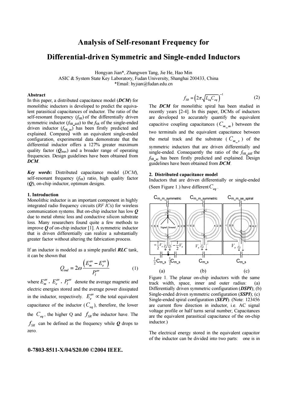
Analysis of Self-resonant Frequency for Differential-driven Symmetric and Single-ended Inductors Hongyan Jian*,Zhangwen Tang,Jie He,Hao Min ASIC System State Key Laboratory,Fudan University,Shanghai 200433,China *Email:hyjian@fudan.edu.cn Abstract In this paper,a distributed capacitance model (DCM)for fow=xC) (2) monolithic inductors is developed to predict the equiva- The DCM for monolithic spiral has been studied in lent parasitical capacitances of inductor.The ratio of the recently years [2-4].In this paper,DCMs of inductors self-resonant frequency (sR)of the differentially driven are developed to accurately quantify the equivalent symmetric inductor (fsR dim)to the fsR of the single-ended driven inductor (fsRs)has been firstly predicted and capacitive coupling capacitances(C)between the explained.Compared with an equivalent single-ended two terminals and the equivalent capacitance between configuration,experimental data demonstrate that the the metal track and the substrate (Cm)of the differential inductor offers a 127%greater maximum symmetric inductors that are driven differentially and quality factor(Omax)and a broader range of operating frequencies.Design guidelines have been obtained from single-ended.Consequently the ratio of the fsRdi the fsR se has been firstly predicted and explained.Design DCM. guidelines have been obtained from DCM. Key words:Distributed capacitance model (DCM, 2.Distributed capacitance model self-resonant frequency (fsR)ratio,high quality factor Inductors that are driven differentially or single-ended (O),on-chip inductor,optimum designs. (Seen Figure 1)have differentC 1.Introduction Monolithic inductor is an important component in highly Cm_m_symmetric Cm_m_symmetric Cm m_se_spiral integrated radio frequency circuits(RF ICs)for wireless communication systems.But on-chip inductor has low O due to metal ohmic loss and conductive silicon substrate loss.Many researchers found quite a few methods to improve o of on-chip inductor [1].A symmetric inductor that is driven differentially can realize a substantially greater factor without altering the fabrication process. If an inductor is modeled as a simple parallel RLC tank, it can be shown that (E-E) Cm_s 2Cm_s Cms Oind =20 (1) (a) (b) (c) Figure 1.The planar on-chip inductors with the same where E,E,pa denote the average magnetic and track width,space,inner and outer radius:(a) electric energies stored and the average power dissipated Differentially driven symmetric configuration (DSP/);(b in the inductor,respectively.Ethe total equivalent Single-ended driven symmetric configuration (SSPD):(c) Single-ended spiral configuration (SEPD).(Note:123456 capacitance of the inductor (C),therefore,the lower are current flow direction in inductor,i.e.AC signal voltage profile or half turns serial number;Capacitances the C the higher Q and Isk the inductor have.The are the equivalent parasitical capacitance of the on-chip Isg can be defined as the frequency while o drops to inductor. zero The electrical energy stored in the equivalent capacitor of the inductor can be divided into two parts:one is in 0-7803-8511-X/04/S20.00©2004EEE.Analysis of Self-resonant Frequency for Differential-driven Symmetric and Single-ended Inductors Hongyan Jian*, Zhangwen Tang, Jie He, Hao Min ASIC & System State Key Laboratory, Fudan University, Shanghai 200433, China *Email: hyjian@fudan.edu.cn Abstract In this paper, a distributed capacitance model (DCM) for monolithic inductors is developed to predict the equivalent parasitical capacitances of inductor. The ratio of the self-resonant frequency (fSR) of the differentially driven symmetric inductor (fSR_diff) to the fSR of the single-ended driven inductor (fSR_se) has been firstly predicted and explained. Compared with an equivalent single-ended configuration, experimental data demonstrate that the differential inductor offers a 127% greater maximum quality factor (Qmax) and a broader range of operating frequencies. Design guidelines have been obtained from DCM. Key words: Distributed capacitance model (DCM), self-resonant frequency (fSR) ratio, high quality factor (Q), on-chip inductor, optimum designs. 1. Introduction Monolithic inductor is an important component in highly integrated radio frequency circuits (RF ICs) for wireless communication systems. But on-chip inductor has low Q due to metal ohmic loss and conductive silicon substrate loss. Many researchers found quite a few methods to improve Q of on-chip inductor [1]. A symmetric inductor that is driven differentially can realize a substantially greater factor without altering the fabrication process. If an inductor is modeled as a simple parallel RLC tank, it can be shown that ( ) 2 av av m e ind av l E E Q P ω − = (1) where av Em , av Ee , av Pl denote the average magnetic and electric energies stored and the average power dissipated in the inductor, respectively. av Ee ∝the total equivalent capacitance of the inductor (Ceq ), therefore, the lower the Ceq , the higher Q and SR f the inductor have. The SR f can be defined as the frequency while Q drops to zero. ( ) 1 2 SR eq eq f LC π − = (2) The DCM for monolithic spiral has been studied in recently years [2-4]. In this paper, DCMs of inductors are developed to accurately quantify the equivalent capacitive coupling capacitances (Cm m_ ) between the two terminals and the equivalent capacitance between the metal track and the substrate ( Cm s _ ) of the symmetric inductors that are driven differentially and single-ended. Consequently the ratio of the fSR_diff the fSR_se has been firstly predicted and explained. Design guidelines have been obtained from DCM. 2. Distributed capacitance model Inductors that are driven differentially or single-ended (Seen Figure 1.) have differentCeq . 1 2 + Vs 1 2 − Vs Vs Vs Signal Ground 1 5 3 4 2 6 1 5 3 4 2 6 1 3 5 6 4 2 Cm_m_symmetric Cm_m_symmetric Cm_m_se_spiral Cm_s Cm_s 0 Cm_s Cm_s 1 2 1 2 (a) (b) (c) Figure 1. The planar on-chip inductors with the same track width, space, inner and outer radius: (a) Differentially driven symmetric configuration (DSPI); (b) Single-ended driven symmetric configuration (SSPI); (c) Single-ended spiral configuration (SEPI). (Note: 123456 are current flow direction in inductor, i.e. AC signal voltage profile or half turns serial number; Capacitances are the equivalent parasitical capacitance of the on-chip inductor.) The electrical energy stored in the equivalent capacitor of the inductor can be divided into two parts: one is in 0-7803-8511-X/04/$20.00 ©2004 IEEE