正在加载图片...

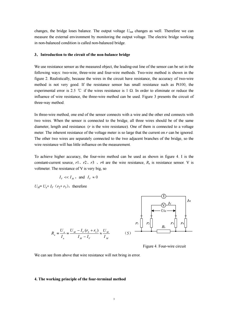
changes,the bridge loses balance.The output voltage out changes as well.Therefore we can measure the external environment by monitoring the output voltage.The electric bridge working in non-balanced condition is called non-balanced bridge. 3.Introduction to the circuit of the non-balance bridge We use resistance sensor as the measured object,the leading-out line of the sensor can be set in the following ways:two-wire,three-wire and four-wire methods.Two-wire method is shown in the figure 2.Realistically,because the wires in the circuit have resistance,the accuracy of two-wire method is not very good.If the resistance sensor has small resistance such as Pt100,the experimental error is 2.5 C if the wires resistance is 1 In order to eliminate or reduce the influence of wire resistance,the three-wire method can be used.Figure 3 presents the circuit of three-way method. In three-wire method,one end of the sensor connects with a wire and the other end connects with two wires.When the sensor is connected to the bridge,all three wires should be of the same diameter,length and resistance.(r is the wire resistance).One of them is connected to a voltage meter.The inherent resistance of the voltage meter is so large that the current onr can be ignored. The other two wires are separately connected to the two adjacent branches of the bridge,so the wire resistance will has little influence on the measurement. To achieve higher accuracy,the four-wire method can be used as shown in figure 4.I is the constant-current source,rl,2,r3r4 are the wire resistance,Rx is resistance sensor.V is voltmeter.The resistance of V is very big,so I<Iy,andI,≈0 UU+Iy (r2+r3),therefore _U._Un-lv(+n)Uu (5) Iv-Iv Figure 4.Four-wire circuit We can see from above that wire resistance will not bring in error. 4.The working principle of the four-terminal method3 changes, the bridge loses balance. The output voltage Uout changes as well. Therefore we can measure the external environment by monitoring the output voltage. The electric bridge working in non-balanced condition is called non-balanced bridge. 3.Introduction to the circuit of the non-balance bridge We use resistance sensor as the measured object, the leading-out line of the sensor can be set in the following ways: two-wire, three-wire and four-wire methods. Two-wire method is shown in the figure 2. Realistically, because the wires in the circuit have resistance, the accuracy of two-wire method is not very good. If the resistance sensor has small resistance such as Pt100, the experimental error is 2.5 ℃ if the wires resistance is 1 Ω. In order to eliminate or reduce the influence of wire resistance, the three-wire method can be used. Figure 3 presents the circuit of three-way method. In three-wire method, one end of the sensor connects with a wire and the other end connects with two wires. When the sensor is connected to the bridge, all three wires should be of the same diameter, length and resistance. (r is the wire resistance). One of them is connected to a voltage meter. The inherent resistance of the voltage meter is so large that the current on r can be ignored. The other two wires are separately connected to the two adjacent branches of the bridge, so the wire resistance will has little influence on the measurement. To achieve higher accuracy, the four-wire method can be used as shown in figure 4. I is the constant-current source, r1、r2、r3 、r4 are the wire resistance, Rx is resistance sensor. V is voltmeter. The resistance of V is very big, so V M I << I ,and ≈ 0 VI UM= Ux+ IV(r2+ r3),therefore M M M V M V x x x I U I I U I r r I U R ≈ − − + = = ( ) 2 3 (5) Figure 4. Four-wire circuit We can see from above that wire resistance will not bring in error. 4. The working principle of the four-terminal method