Experiment 3 Application of balanced and non-balanced Wheatstone Bridges In 1843,the English physicist,Sir Charles Wheatstone (1802-1875)found a bridge circuit for measuring electric resistance.Nowadays,Wheatstone bridge is a common method to measure the resistance ranging from 10 to 100.In the bridge circuit,unknown resistances are comparable to the well-known resistances under balance condition.However,for small resistance less than 100. the unknown resistance cannot be measured using Wheatstone bridge due to contact resistance with a typical magnitude of 10.Thus the four probe method is used to measure small resistance around 10 or less precluding the effect of contact resistance and wire resistance.By measuring the voltage across the resistors and the current flowing through it,we can determine the resistance. Because of its outstanding characteristics,the Four Probe Method is applicable to all types of resistance measurement,especially to the low-value resistance measurements.The Wheatstone bridge can be useful for the measurement of small changes of resistance under non-balanced condition.Replacing one resistance in bridge by a sensor such as resistance thermometer or strain gauge,the changes of the sensor's resistance responding to the external environment can be obtained.Though non-balanced bridge,the resistance can be transformed into current that we can easily measure and manipulate. 【Objective】 1.Determine unknown resistances by balanced Wheatstone bridge; 2.Use the four probe method to measure the resistivity of metal wire; 3.Understand the principle of non-balanced bridge; 4.Learn the principle of some sensors.Measure its resistance using non-balanced bridge. 【Principle)】 1.The principle of balanced Wheatstone bridge A Wheatstone bridge can be used to accurately determine an object's resistance.As shown in figure 1,U is power supply;R and R2 are resistors of known resistance;the resistance of Rp is adjustable;Rx is the unknown resistance to be measured;Uout is the output voltage of the bridge.When Uout=0,the bridge is in a balance state.Then R Rp =R2R, (1) Thus the unknown resistance can be calculated R=1 (2) R, Notice that the computed R does not depend on the voltage of power supply.In addition,the ratio of Ri/R2 should be chosen properly so as to obtain R with enough significant figures
1 Experiment 3 Application of balanced and non-balanced Wheatstone Bridges In 1843, the English physicist, Sir Charles Wheatstone (1802-1875) found a bridge circuit for measuring electric resistance. Nowadays, Wheatstone bridge is a common method to measure the resistance ranging from 10 to 106 Ω. In the bridge circuit, unknown resistances are comparable to the well-known resistances under balance condition. However, for small resistance less than 10Ω, the unknown resistance cannot be measured using Wheatstone bridge due to contact resistance with a typical magnitude of 10-2Ω. Thus the four probe method is used to measure small resistance around 10-1Ω or less precluding the effect of contact resistance and wire resistance. By measuring the voltage across the resistors and the current flowing through it, we can determine the resistance. Because of its outstanding characteristics, the Four Probe Method is applicable to all types of resistance measurement, especially to the low-value resistance measurements. The Wheatstone bridge can be useful for the measurement of small changes of resistance under non-balanced condition. Replacing one resistance in bridge by a sensor such as resistance thermometer or strain gauge, the changes of the sensor’s resistance responding to the external environment can be obtained. Though non-balanced bridge, the resistance can be transformed into current that we can easily measure and manipulate. 【Objective】 1. Determine unknown resistances by balanced Wheatstone bridge; 2. Use the four probe method to measure the resistivity of metal wire; 3. Understand the principle of non-balanced bridge; 4. Learn the principle of some sensors. Measure its resistance using non-balanced bridge. 【Principle】 1. The principle of balanced Wheatstone bridge A Wheatstone bridge can be used to accurately determine an object’s resistance. As shown in figure 1, U is power supply; R1 and R2 are resistors of known resistance; the resistance of RP is adjustable; Rx is the unknown resistance to be measured; Uout is the output voltage of the bridge.When Uout = 0,the bridge is in a balance state .Then R1RP = R2Rx (1) Thus the unknown resistance can be calculated x Rp R R R 2 1 = (2) Notice that the computed Rx does not depend on the voltage of power supply. In addition, the ratio of R1 /R2 should be chosen properly so as to obtain Rx with enough significant figures
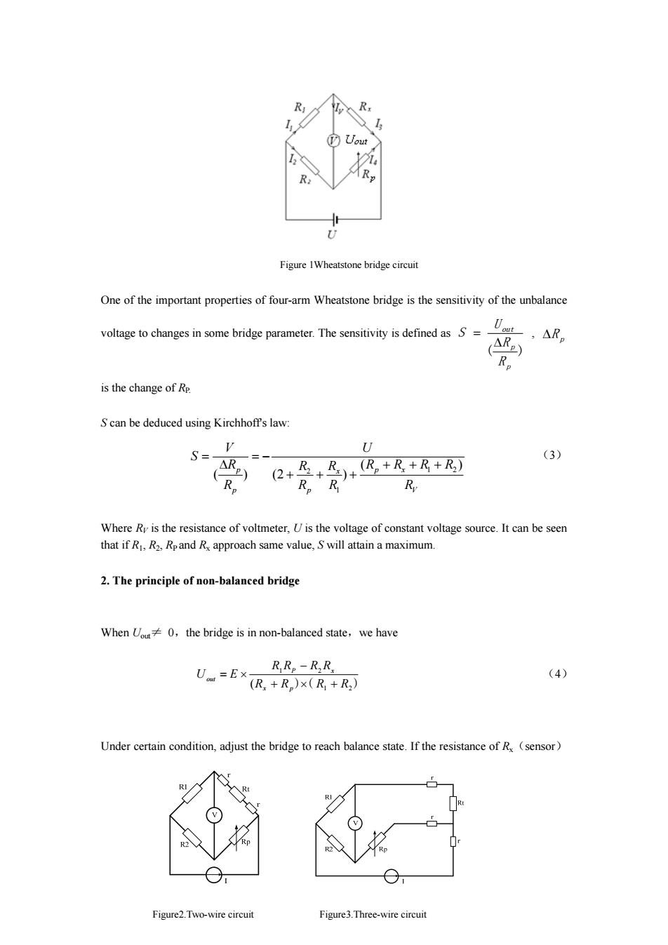
R Uout R U Figure 1Wheatstone bridge circuit One of the important properties of four-arm Wheatstone bridge is the sensitivity of the unbalance voltage to changes in some bridge parameter.The sensitivity is defined as S= (ARB) Rp is the change of Re S can be deduced using Kirchhoff's law: S=- V U (3) △ ) +B+)+区,+R+R+B (2 Rp R。R R Where Ry is the resistance of voltmeter,U is the voltage of constant voltage source.It can be seen that if R,R2,Rpand Rx approach same value,S will attain a maximum. 2.The principle of non-balanced bridge When Uou 0,the bridge is in non-balanced state,we have R Re-RR Uom =Ex- (4) (R+R)×(R+R2) Under certain condition,adjust the bridge to reach balance state.If the resistance of R(sensor) RI RI R② Figure2.Two-wire circuit Figure3.Three-wire circuit
2 Figure 1Wheatstone bridge circuit One of the important properties of four-arm Wheatstone bridge is the sensitivity of the unbalance voltage to changes in some bridge parameter. The sensitivity is defined as ( ) p p out R R U S Δ = , ΔR p is the change of RP. S can be deduced using Kirchhoff's law: V x p x p p p R R R R R R R R R U R R V S ( ) ( ) (2 ) 1 2 1 2 + + + + + + = − Δ = (3) Where RV is the resistance of voltmeter, U is the voltage of constant voltage source. It can be seen that if R1, R2, RP and Rx approach same value, S will attain a maximum. 2. The principle of non-balanced bridge When Uout≠ 0,the bridge is in non-balanced state,we have )( 1 2 ) 1 2 (R R R R R R R R U E x p P x out + × + − = × (4) Under certain condition, adjust the bridge to reach balance state. If the resistance of Rx(sensor) Figure2.Two-wire circuit Figure3.Three-wire circuit
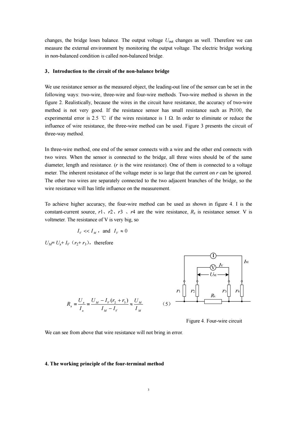
changes,the bridge loses balance.The output voltage out changes as well.Therefore we can measure the external environment by monitoring the output voltage.The electric bridge working in non-balanced condition is called non-balanced bridge. 3.Introduction to the circuit of the non-balance bridge We use resistance sensor as the measured object,the leading-out line of the sensor can be set in the following ways:two-wire,three-wire and four-wire methods.Two-wire method is shown in the figure 2.Realistically,because the wires in the circuit have resistance,the accuracy of two-wire method is not very good.If the resistance sensor has small resistance such as Pt100,the experimental error is 2.5 C if the wires resistance is 1 In order to eliminate or reduce the influence of wire resistance,the three-wire method can be used.Figure 3 presents the circuit of three-way method. In three-wire method,one end of the sensor connects with a wire and the other end connects with two wires.When the sensor is connected to the bridge,all three wires should be of the same diameter,length and resistance.(r is the wire resistance).One of them is connected to a voltage meter.The inherent resistance of the voltage meter is so large that the current onr can be ignored. The other two wires are separately connected to the two adjacent branches of the bridge,so the wire resistance will has little influence on the measurement. To achieve higher accuracy,the four-wire method can be used as shown in figure 4.I is the constant-current source,rl,2,r3r4 are the wire resistance,Rx is resistance sensor.V is voltmeter.The resistance of V is very big,so I<Iy,andI,≈0 UU+Iy (r2+r3),therefore _U._Un-lv(+n)Uu (5) Iv-Iv Figure 4.Four-wire circuit We can see from above that wire resistance will not bring in error. 4.The working principle of the four-terminal method
3 changes, the bridge loses balance. The output voltage Uout changes as well. Therefore we can measure the external environment by monitoring the output voltage. The electric bridge working in non-balanced condition is called non-balanced bridge. 3.Introduction to the circuit of the non-balance bridge We use resistance sensor as the measured object, the leading-out line of the sensor can be set in the following ways: two-wire, three-wire and four-wire methods. Two-wire method is shown in the figure 2. Realistically, because the wires in the circuit have resistance, the accuracy of two-wire method is not very good. If the resistance sensor has small resistance such as Pt100, the experimental error is 2.5 ℃ if the wires resistance is 1 Ω. In order to eliminate or reduce the influence of wire resistance, the three-wire method can be used. Figure 3 presents the circuit of three-way method. In three-wire method, one end of the sensor connects with a wire and the other end connects with two wires. When the sensor is connected to the bridge, all three wires should be of the same diameter, length and resistance. (r is the wire resistance). One of them is connected to a voltage meter. The inherent resistance of the voltage meter is so large that the current on r can be ignored. The other two wires are separately connected to the two adjacent branches of the bridge, so the wire resistance will has little influence on the measurement. To achieve higher accuracy, the four-wire method can be used as shown in figure 4. I is the constant-current source, r1、r2、r3 、r4 are the wire resistance, Rx is resistance sensor. V is voltmeter. The resistance of V is very big, so V M I << I ,and ≈ 0 VI UM= Ux+ IV(r2+ r3),therefore M M M V M V x x x I U I I U I r r I U R ≈ − − + = = ( ) 2 3 (5) Figure 4. Four-wire circuit We can see from above that wire resistance will not bring in error. 4. The working principle of the four-terminal method
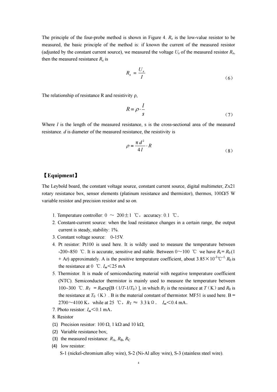
The principle of the four-probe method is shown in Figure 4.Rx is the low-value resistor to be measured,the basic principle of the method is:if known the current of the measured resistor (adjusted by the constant current source),we measured the voltage U of the measured resistor R, then the measured resistance R,is R,= (6) The relationship of resistance R and resistivity p, R=P.- (7) Where is the length of the measured resistance,s is the cross-sectional area of the measured resistance.d is diameter of the measured resistance,the resistivity is psπd …R 41 (8) 【Equipment】. The Leybold board,the constant voltage source,constant current source,digital multimeter,Zx21 rotary resistance box,sensor elements(platinum resistance and thermistor),thermos,1000/5 W variable resistor and precision resistor and so on. 1.Temperature controller:0~200±1℃,accuracy:0.l℃. 2.Constant-current source:when the load resistance changes in a certain range,the output current is steady,stability:1%. 3.Constant voltage source:0-15V. 4.Pt resistor:Pt100 is used here.It is wildly used to measure the temperature between -200~850 C.It is accurate,sensitive and stable.Between 0~100 C we have R=Ro(1 +Ar)approximately.A is the positive temperature coefficient,about 3.85X10CRois the resistance at 0 C.Im<25 mA 5.Thermistor.It is made of semiconducting material with negative temperature coefficient (NTC).Semiconductor thermistor is mainly used to measure the temperature between 100~300 C.Rr =Roexp[B (1/T-1/To)],in which Rr is the resistance at T(K)and Ro is the resistance at To (K).B is the material constant of thermistor.MF51 is used here.B= 2700~4100K,while at25℃,Rr≈3.3k2.Im<0.4mA. 7.Photo resistor:I<0.1 mA. 8.Resistor (1)Precision resistor:100 1 k and 10 k; (2)Variable resistance box; (3)the measured resistance:RA,RB,Rc (4)low resistor: S-1(nickel-chromium alloy wire),S-2(Ni-Al alloy wire),S-3(stainless steel wire)
4 The principle of the four-probe method is shown in Figure 4. Rx is the low-value resistor to be measured, the basic principle of the method is: if known the current of the measured resistor (adjusted by the constant current source), we measured the voltage Ux of the measured resistor Rx, then the measured resistance Rx is I U R x x = (6) The relationship of resistance R and resistivity ρ, R = ρ ⋅ l s (7) Where l is the length of the measured resistance, s is the cross-sectional area of the measured resistance. d is diameter of the measured resistance, the resistivity is R l d ⋅ π = 4 2 ρ (8) 【Equipment】 The Leybold board, the constant voltage source, constant current source, digital multimeter, Zx21 rotary resistance box, sensor elements (platinum resistance and thermistor), thermos, 100Ω/5 W variable resistor and precision resistor and so on. 1. Temperature controller: 0 ~ 200±1 ℃,accuracy: 0.1 ℃. 2. Constant-current source: when the load resistance changes in a certain range, the output current is steady, stability: 1%. 3. Constant voltage source: 0-15V. 4. Pt resistor: Pt100 is used here. It is wildly used to measure the temperature between -200~850 ℃. It is accurate, sensitive and stable. Between 0~100 ℃ we have Rt = R0 (1 + At) approximately. A is the positive temperature coefficient, about 3.85×10⁻³℃-1. R0 is the resistance at 0 ℃. Im<25 mA 5. Thermistor. It is made of semiconducting material with negative temperature coefficient (NTC). Semiconductor thermistor is mainly used to measure the temperature between 100~300 ℃. RT = R0exp[B(1/T-1/T0)], in which RT is the resistance at T(K)and R0 is the resistance at T0(K). B is the material constant of thermistor. MF51 is used here. B = 2700~4100 K,while at 25 ℃,RT ≈ 3.3 kΩ. Im<0.4 mA. 7. Photo resistor: Im<0.1 mA. 8. Resistor (1) Precision resistor: 100 Ω, 1 kΩ and 10 kΩ; (2) Variable resistance box; (3) the measured resistance: RA, RB, RC (4) low resistor: S-1 (nickel-chromium alloy wire), S-2 (Ni-Al alloy wire), S-3 (stainless steel wire)
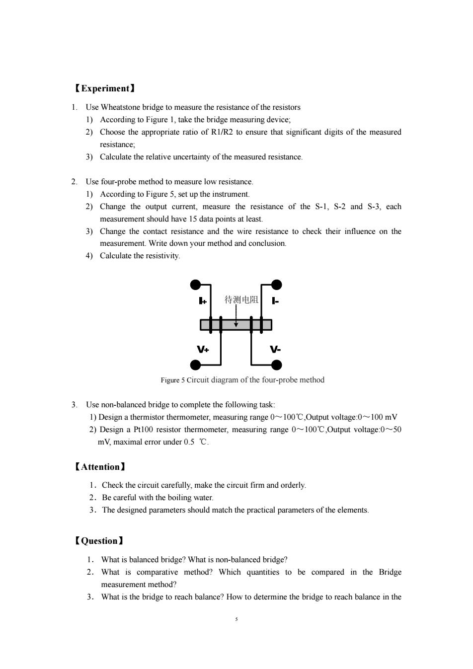
【Experiment】. 1.Use Wheatstone bridge to measure the resistance of the resistors 1)According to Figure 1,take the bridge measuring device; 2)Choose the appropriate ratio of R1/R2 to ensure that significant digits of the measured resistance: 3)Calculate the relative uncertainty of the measured resistance 2.Use four-probe method to measure low resistance. 1)According to Figure 5,set up the instrument. 2)Change the output current,measure the resistance of the S-1,S-2 and S-3,each measurement should have 15 data points at least. 3)Change the contact resistance and the wire resistance to check their influence on the measurement.Write down your method and conclusion. 4)Calculate the resistivity. 待测电阻 V Figure 5 Circuit diagram of the four-probe method 3.Use non-balanced bridge to complete the following task: 1)Design a thermistor thermometer,measuring range 0~100C,Output voltage:0~100 mV 2)Design a Pt100 resistor thermometer,measuring range 0~100C,Output voltage:0~50 mV,maximal error under 0.5 C. 【Attention】 1.Check the circuit carefully,make the circuit firm and orderly. 2.Be careful with the boiling water. 3.The designed parameters should match the practical parameters of the elements. 【Question】 1.What is balanced bridge?What is non-balanced bridge? 2.What is comparative method?Which quantities to be compared in the Bridge measurement method? 3.What is the bridge to reach balance?How to determine the bridge to reach balance in the 5
5 【Experiment】 1. Use Wheatstone bridge to measure the resistance of the resistors 1) According to Figure 1, take the bridge measuring device; 2) Choose the appropriate ratio of R1/R2 to ensure that significant digits of the measured resistance; 3) Calculate the relative uncertainty of the measured resistance. 2. Use four-probe method to measure low resistance. 1) According to Figure 5, set up the instrument. 2) Change the output current, measure the resistance of the S-1, S-2 and S-3, each measurement should have 15 data points at least. 3) Change the contact resistance and the wire resistance to check their influence on the measurement. Write down your method and conclusion. 4) Calculate the resistivity. Figure 5 Circuit diagram of the four-probe method 3. Use non-balanced bridge to complete the following task: 1) Design a thermistor thermometer, measuring range 0~100℃,Output voltage:0~100 mV 2) Design a Pt100 resistor thermometer, measuring range 0~100℃,Output voltage:0~50 mV, maximal error under 0.5 ℃. 【Attention】 1.Check the circuit carefully, make the circuit firm and orderly. 2.Be careful with the boiling water. 3.The designed parameters should match the practical parameters of the elements. 【Question】 1. What is balanced bridge? What is non-balanced bridge? 2. What is comparative method? Which quantities to be compared in the Bridge measurement method? 3. What is the bridge to reach balance? How to determine the bridge to reach balance in the

experiment? 4.Write the steps to take the bridge measuring device 5.As for Pt resistor,thermistor,what are the factors that cause the non-linear error between output voltage and temperature?Please estimate the error that will possibly occur.What will you do to avoid it? 6.Please analyze theoretically from figure 2 and 3,why the three-wire circuit can reduce the error compared to two-wire circuit? 7.Should the internal resistance of multimeter be considered?Why? 8.What main factors will you take into consideration while design the circuit,why? 9.According to the experimental result,do you think it achieves your design requirement? 10.How to choose the ratio of R and R2 properly? 11.How to improve the measurement accuracy when measuring resistance using bridge method? 12.According to experimental phenomena,analyses why digital voltmeter of high input impedance can eliminate the influence of the contact resistance and wire resistance. 【Reference】 [山薛文达,谢文和,张呈祥编。传感器应用技术.南京:东南大学出版社。 [2]吕斯弊,段家忯主编.基础物理实验.北京:北京大学出版社,2002 [3】黄贤武,郑筱霞编。传感器原理与应用.成都:电子科技大学出版社,1999
6 experiment? 4. Write the steps to take the bridge measuring device. 5. As for Pt resistor, thermistor, what are the factors that cause the non-linear error between output voltage and temperature? Please estimate the error that will possibly occur. What will you do to avoid it? 6. Please analyze theoretically from figure 2 and 3, why the three-wire circuit can reduce the error compared to two-wire circuit? 7. Should the internal resistance of multimeter be considered? Why? 8.What main factors will you take into consideration while design the circuit, why? 9.According to the experimental result, do you think it achieves your design requirement? 10. How to choose the ratio of R1 and R2 properly? 11. How to improve the measurement accuracy when measuring resistance using bridge method? 12. According to experimental phenomena, analyses why digital voltmeter of high input impedance can eliminate the influence of the contact resistance and wire resistance. 【Reference】 [1] 薛文达,谢文和,张呈祥编.传感器应用技术.南京:东南大学出版社. [2] 吕斯骅,段家忯主编.基础物理实验.北京:北京大学出版社,2002 [3] 黄贤武,郑筱霞编.传感器原理与应用.成都:电子科技大学出版社,1999
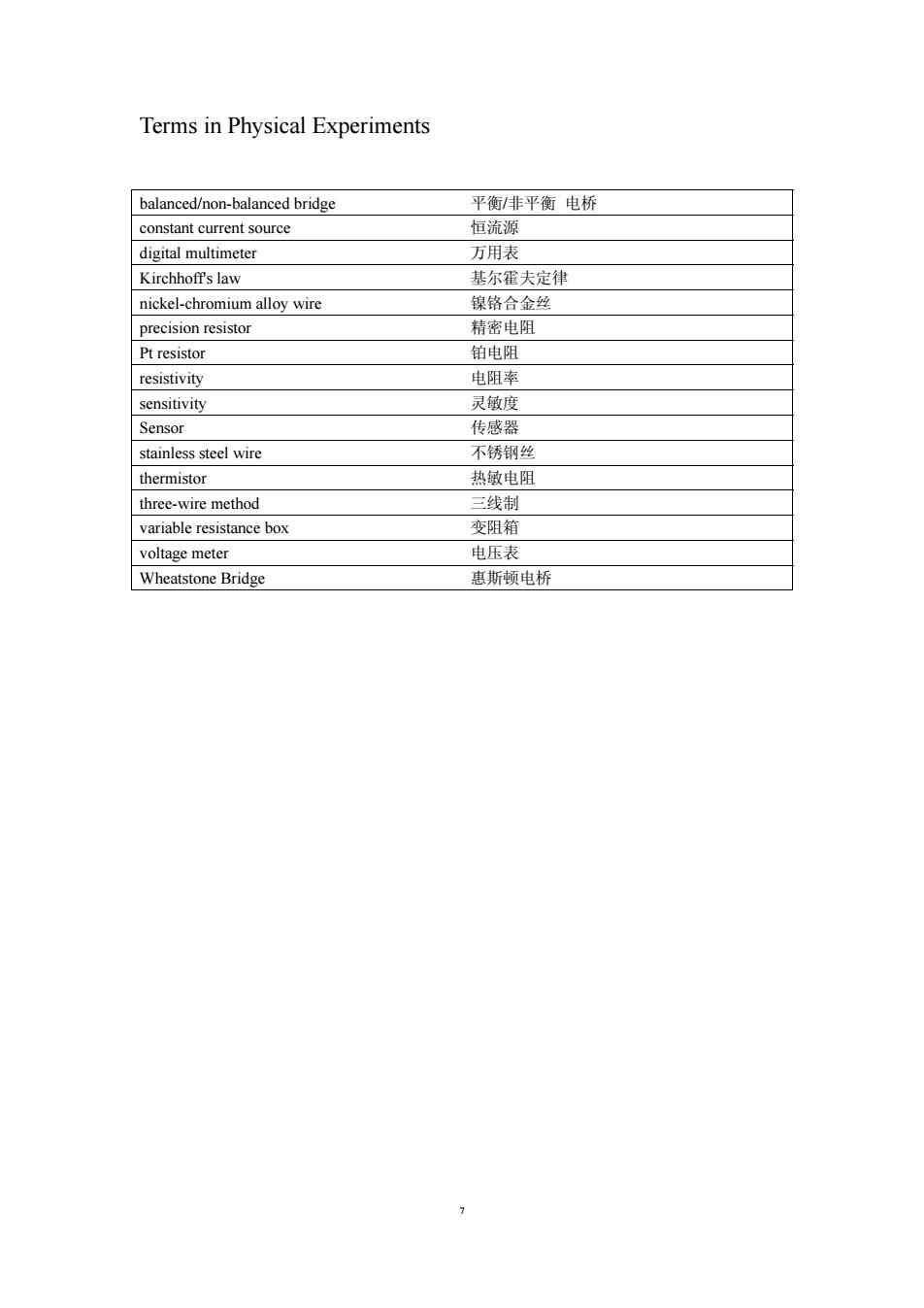
Terms in Physical Experiments balanced/non-balanced bridge 平衡/非平衡电桥 constant current source 恒流源 digital multimeter 万用表 Kirchhoff's law 基尔霍夫定律 nickel-chromium alloy wire 镍铬合金丝 precision resistor 精密电阻 Pt resistor 铂电阻 resistivity 电阻率 sensitivity 灵敏度 Sensor 传感器 stainless steel wire 不锈钢丝 thermistor 热敏电阻 three-wire method 三线制 variable resistance box 变阻箱 voltage meter 电压表 Wheatstone Bridge 惠斯顿电桥
7 Terms in Physical Experiments balanced/non-balanced bridge 平衡/非平衡 电桥 constant current source 恒流源 digital multimeter 万用表 Kirchhoff's law 基尔霍夫定律 nickel-chromium alloy wire 镍铬合金丝 precision resistor 精密电阻 Pt resistor 铂电阻 resistivity 电阻率 sensitivity 灵敏度 Sensor 传感器 stainless steel wire 不锈钢丝 thermistor 热敏电阻 three-wire method 三线制 variable resistance box 变阻箱 voltage meter 电压表 Wheatstone Bridge 惠斯顿电桥