Experiment 2 Practice and Application of Michelson Interferometer The wave properties of light lead to interference.If when two light beams originated from one light meet at the same spot after traveling along different paths,optical interference occurs if the optical path difference is smaller than coherence length of light.Michelson interferometer is a precise instrument to achieve light interference by divide the amplitude of light wave invented by Michelson 1881.Utilizing this interferometer,Michelson accomplished three very famous experiments:Michelson-Morley experiment to deny the existence of Ether,fine structures of optical spectrum and length unit calibration by light wavelength.Michelson Interferometer has simple optical design,intuitional light path and high precision.The adjustment and usage of Michelson interferometer is a very important training in optics.Many precise instruments based on the principle of Michelson Interferometer have been widely used in scientific research as well as industry. 【Objectives.】 1.Understand the basic principle and structure of Michelson Interferometer and be able to adjust Michelson Interferometer 2.Observe localized equal-inclination interference,equal thickness interference (white light interference),and non-localized interference. 3.Measure the light wavelength and understand the physics of the visibility of stripe 【Principle】 1.The principle and structure of Michelson Interferometer The typical light path of Michelson Interferometer is shown in Figure1. M2 光源 G 2 G2 E Figure I the typical light path of Michelson Interferometer As shown in Fig.1,MI and M2 are two plane mirrors mounted on two arms perpendicular to each other.The position of Ml is fixed and M2 can be moved along the direction of the arm through
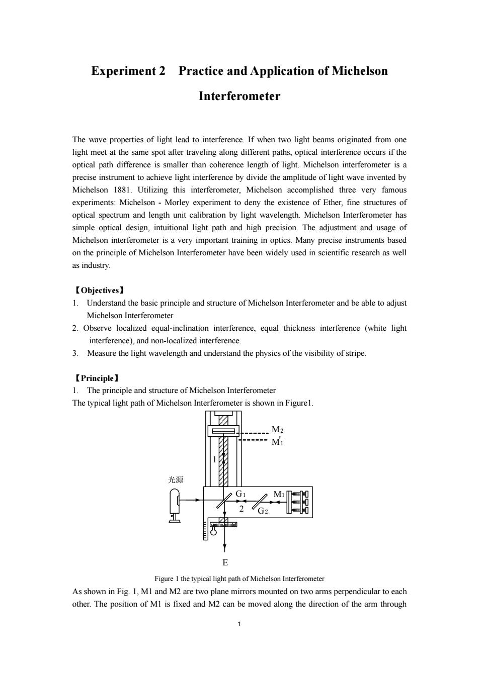
1 Experiment 2 Practice and Application of Michelson Interferometer The wave properties of light lead to interference. If when two light beams originated from one light meet at the same spot after traveling along different paths, optical interference occurs if the optical path difference is smaller than coherence length of light. Michelson interferometer is a precise instrument to achieve light interference by divide the amplitude of light wave invented by Michelson 1881. Utilizing this interferometer, Michelson accomplished three very famous experiments: Michelson - Morley experiment to deny the existence of Ether, fine structures of optical spectrum and length unit calibration by light wavelength. Michelson Interferometer has simple optical design, intuitional light path and high precision. The adjustment and usage of Michelson interferometer is a very important training in optics. Many precise instruments based on the principle of Michelson Interferometer have been widely used in scientific research as well as industry. 【Objectives】 1. Understand the basic principle and structure of Michelson Interferometer and be able to adjust Michelson Interferometer 2. Observe localized equal-inclination interference, equal thickness interference (white light interference), and non-localized interference. 3. Measure the light wavelength and understand the physics of the visibility of stripe. 【Principle】 1. The principle and structure of Michelson Interferometer The typical light path of Michelson Interferometer is shown in Figure1. M2 M1 ' M1 G2 G1 2 1 光源 E Figure 1 the typical light path of Michelson Interferometer As shown in Fig. 1, M1 and M2 are two plane mirrors mounted on two arms perpendicular to each other. The position of M1 is fixed and M2 can be moved along the direction of the arm through
adjusting a precise screw.The inclination angle of M2 is fixed and that of MI can be changed by the screw on the back of it.GI and G2 are two absolutely identical glasses.The backside of the GI glass is properly coated by silver.50%of the incident light can pass through Gl and 50%of the light is reflected.We call Gl as light splitter or beam splitter.The angle between Gl(G2)and MI(M2)is 45 degree.The beam from the light source splits into beam 1(reflection)and beam 2 (transmission)by beam-splitter G1.Beaml and beam2 are then reflected back by Ml and M2 irrespectively.At last,two coherent beams meet at GI and interfere with each other.G2 is called as compensation glass.Known from the light path,both beaml and beam 2 pass glass three times, which ensures that the optical path difference between beaml and beam 2 will not be too big.G2 is very important to the light source with poor monochromaticity. MI forms a virtual image(MI')near M2 due to the reflection of Gl,so the interference between beam I and beam 2 is equivalent to the interference caused by the air film between M2 and MI'. 2.Equal inclination interference(localized interference) Shown in the Fig.2,a light beam y with wavelength A is reflected at M2 and MI'with an interval distance d.The reflected beams are yl and y2. B b D M Figure 2.The light path of equal inclination interference If we set the optical path of yl is l and that of y2 is l+Al the difference of optical path isAl, where Al=AB+BD.If the incident angle is 0,so Al=2d cos0 When Al=2d cose=kA,bright stripes =2dcos0=(k+,dark stripes 2 where k is an integer,called interference order number. When MI'and M2 is parallel to each other,one can see alternately dark and bright rings. This configuration is called equal inclination interference.One bright ring will generate or vanish in the center of the sight field when increasing or decreasing d by 4/2 by moving M2 mirror.The relation between the number difference of rings AN and M2 movement Ad can be expressed by: △d=△N×2/2 (1) So the wavelength can be measured through equation(1). With the increasing of d,k increases,which means that the order of the center of interference
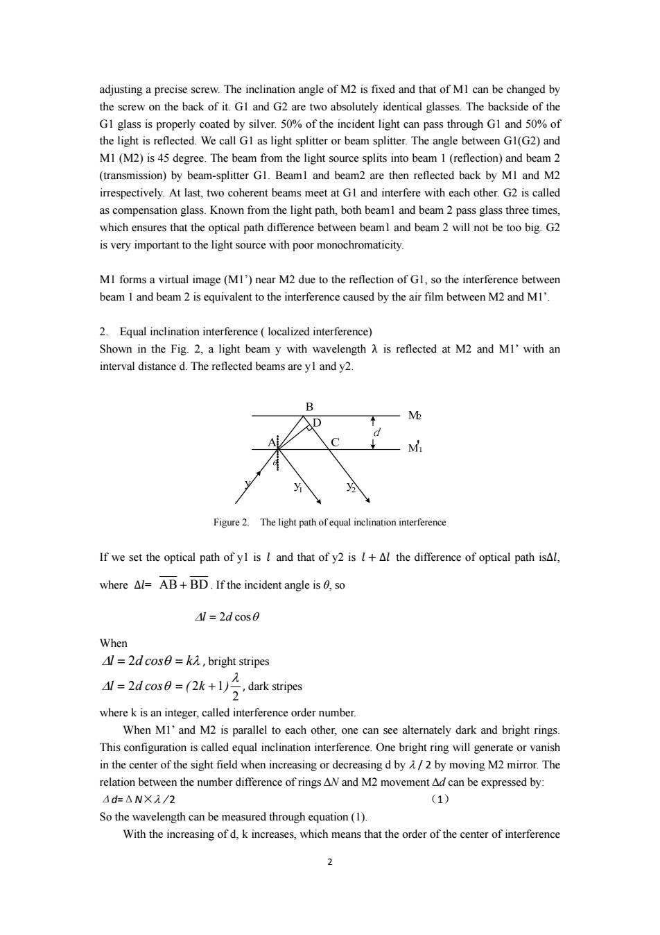
2 adjusting a precise screw. The inclination angle of M2 is fixed and that of M1 can be changed by the screw on the back of it. G1 and G2 are two absolutely identical glasses. The backside of the G1 glass is properly coated by silver. 50% of the incident light can pass through G1 and 50% of the light is reflected. We call G1 as light splitter or beam splitter. The angle between G1(G2) and M1 (M2) is 45 degree. The beam from the light source splits into beam 1 (reflection) and beam 2 (transmission) by beam-splitter G1. Beam1 and beam2 are then reflected back by M1 and M2 irrespectively. At last, two coherent beams meet at G1 and interfere with each other. G2 is called as compensation glass. Known from the light path, both beam1 and beam 2 pass glass three times, which ensures that the optical path difference between beam1 and beam 2 will not be too big. G2 is very important to the light source with poor monochromaticity. M1 forms a virtual image (M1’) near M2 due to the reflection of G1, so the interference between beam 1 and beam 2 is equivalent to the interference caused by the air film between M2 and M1’. 2. Equal inclination interference ( localized interference) Shown in the Fig. 2, a light beam y with wavelength λ is reflected at M2 and M1’ with an interval distance d. The reflected beams are y1 and y2. Figure 2. The light path of equal inclination interference If we set the optical path of y1 is ݈ and that of y2 is ݈ ∆݈ the difference of optical path is∆݈, where ∆݈= AB + BD . If the incident angle is θ, so Δl = 2d cosθ When Δl = 2d cosθ = kλ , bright stripes 2 2 2 1 λ Δl = d cosθ = ( k + ) , dark stripes where k is an integer, called interference order number. When M1’ and M2 is parallel to each other, one can see alternately dark and bright rings. This configuration is called equal inclination interference. One bright ring will generate or vanish in the center of the sight field when increasing or decreasing d by λ / 2 by moving M2 mirror. The relation between the number difference of rings ΔN and M2 movement Δd can be expressed by: Δd=ΔN×λ / 2 (1) So the wavelength can be measured through equation (1). With the increasing of d, k increases, which means that the order of the center of interference
pattern increases.Correspondingly,the center of the rings continuously produces new rings and vice versa.Figure 3a) M2 M2 M2 M -----一M1 M1-----M1 M2 M2 〔a) M2 M2 M --=-M --MI -M2 M2 M2 〔b) Figure 3 interference patterns If MI'and M2 are not parallel to each other,one can observe equal thickness interference patterns.Sometimes the pattern bends slightly.(See Figure 3b) If the incident light has two wavelengths or finite width of wavelength,the changes of interference stripes according to the optical path and the visibility of the stripes differs periodically. For example,suppose the incident light includes two wavelengths(,A).We have: 2d=k,the interference stripes related to are bright. 2d=(k+ the interferenripes related tea If we have: 2d2d_1(2) Then the bright stripes for overlap the dark stripes for which makes the interference patterns obscure When the d is changed to d',and d'satisfies 2d=k,the interference stripes are bright 2d'=k,+,the interference stripes are bright
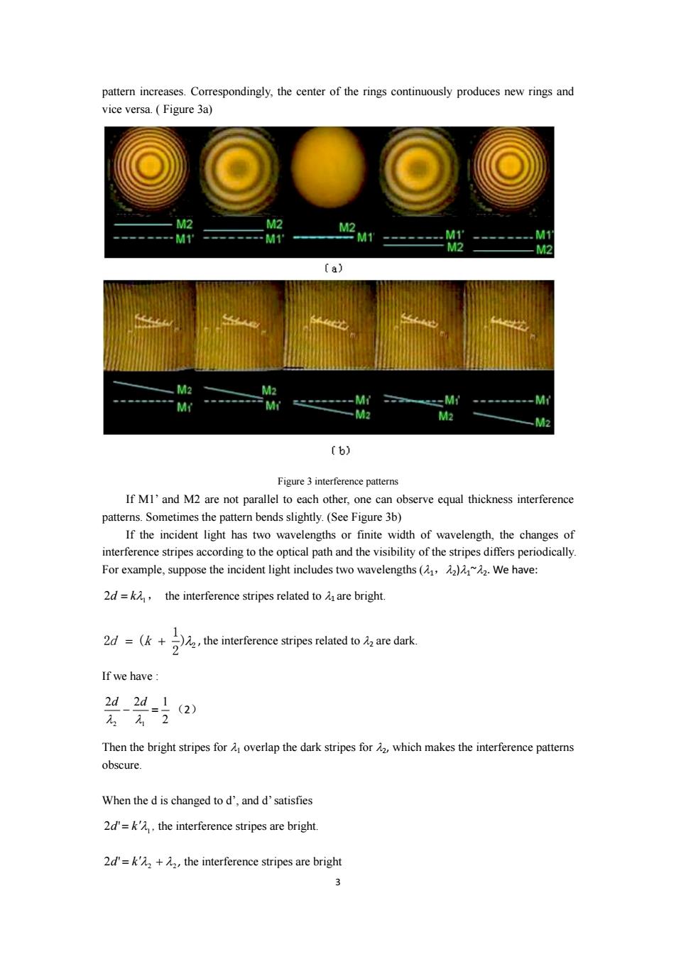
3 pattern increases. Correspondingly, the center of the rings continuously produces new rings and vice versa. ( Figure 3a) Figure 3 interference patterns If M1’ and M2 are not parallel to each other, one can observe equal thickness interference patterns. Sometimes the pattern bends slightly. (See Figure 3b) If the incident light has two wavelengths or finite width of wavelength, the changes of interference stripes according to the optical path and the visibility of the stripes differs periodically. For example, suppose the incident light includes two wavelengths (λ1,λ2)λ1~λ2. We have: 2 λ1 d = k , the interference stripes related to λ1 are bright. 2 ) 2 1 2d = (k + λ , the interference stripes related to λ2 are dark. If we have : 2 2 2 1 2 1 − = λ λ d d (2) Then the bright stripes for λ1 overlap the dark stripes for λ2, which makes the interference patterns obscure. When the d is changed to d’, and d’ satisfies 1 2d'= k′λ , the interference stripes are bright. 2 2 2d'= k′λ + λ , the interference stripes are bright
The stripes become clear. When the d'is changed to d",and d"satisfies 2d"=k"A,the interference stripes are bright 3 2d"=k"元2+ 2 the interference stripes are dark 2d”2d"3 (3) 元212 The stripes in the sight field become obscure again.So there is oscillation. We do (3)-(2)and get: 2Ad1-)=1(4) where Ad d"-d,ifh,then= 42=(2-)=2Ad (5) So the distance Ad for neighboring obscure stripes when moving M2 can be used to determine the wavelength difference A1. 3.Non-localized interference ,M2 ■■■■■■ Figure 4 non-localized interference As shown in Figure 4,the light emitted by a spot light source is reflected by MI'and M2 acting as emitted from two virtual light source S1 and S2.The separation of SI and S2 is double of that of MI'and M2.The interference pattern can be seen everywhere in the light-field-overlapped region, so called non-localized interference. 【Instrument】 WSM-100 Michelson Interferometer,Sodium lamp,frosted glass screen,CCD,lens,computer, laser,beam expander,incandescent lamp
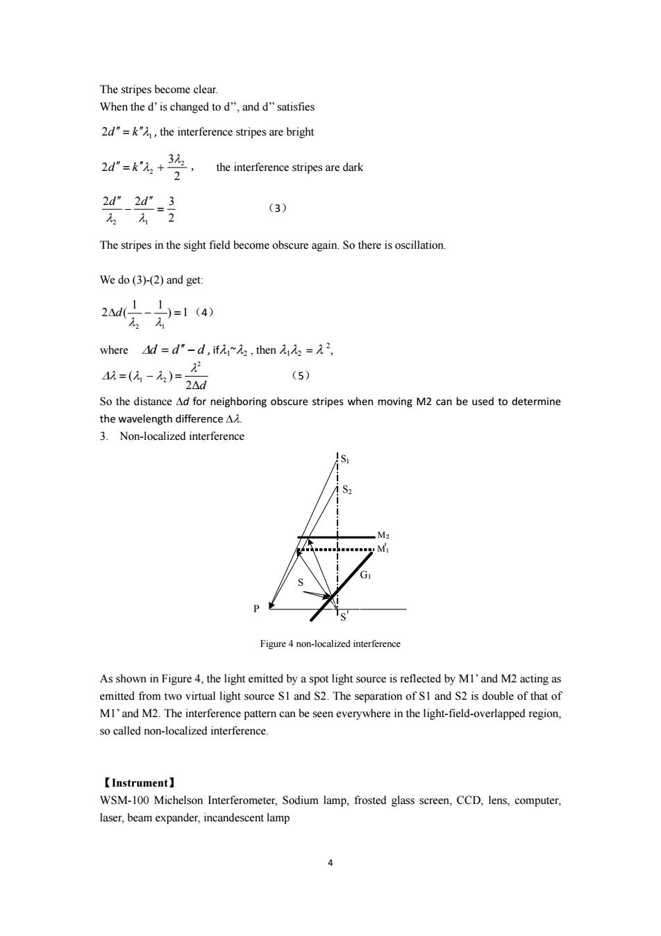
4 The stripes become clear. When the d’ is changed to d’’, and d’’ satisfies 2 λ1 d ′′ = k′′ , the interference stripes are bright 2 3 2 2 2 λ d ′′ = k ′′λ + , the interference stripes are dark 2 2 2 3 2 1 = ′′ − ′′ λ λ d d (3) The stripes in the sight field become obscure again. So there is oscillation. We do (3)-(2) and get: ) 1 1 1 2 ( 2 1 Δ − = λ λ d (4) where Δd = d ′′ − d , ifλ1~λ2 , then λ1λ2 = λ 2 , 2Δd ( ) 2 1 2 λ Δλ = λ − λ = (5) So the distance Δd for neighboring obscure stripes when moving M2 can be used to determine the wavelength difference Δλ. 3. Non-localized interference G1 S S2 P M' 1 M2 S' S1 Figure 4 non-localized interference As shown in Figure 4, the light emitted by a spot light source is reflected by M1’ and M2 acting as emitted from two virtual light source S1 and S2. The separation of S1 and S2 is double of that of M1’ and M2. The interference pattern can be seen everywhere in the light-field-overlapped region, so called non-localized interference. 【Instrument】 WSM-100 Michelson Interferometer, Sodium lamp, frosted glass screen, CCD, lens, computer, laser, beam expander, incandescent lamp
【Experiment】 1.Adjust Michelson Interferometer and observe the equal inclination interference pattern 1)Put a piece of frosted glass in the front of Sodium lamp to get a plane light source. 2)Move M2 to have the same distance between M1 and Glas that between M2 and G2 3)Put a black board with a small hole on the frosted glass to get a spot light.The hole and GI should have the same height. 4)There will have at least three reflected spots from M1,M2 and GI at E.By slightly adjusting the screws on the back of MI,spot due to the reflection from MI will move accordingly.All three spots can be identified using the same method.Spots from MI and M2 have the largest intensity.Try to make two high intensity spots completely coincide at center of the sight field,then MI'and M2 is very close to absolutely parallel.Now remove the black board with a small hole,usually you should be able to observe the interference pattern.If the interference stripes are invisible or obscure,try to move M2 a little or put back the black board to recheck position of the two bright spots.Repeat the above process until the interference pattern appears. 5)If the interference rings are not concentric or the center of the rings is not at the center of sight field,please adjust the spring screw on the back of MI extremely slightly to make them concentric.Now moving your observing eye up-down and right-left,if the rings emerge (merge)from (into)the center,we need to fine tuning the horizontal tension spring screws and the vertical tension spring screws to eliminate the above phenomena. Finally MI'is absolutely parallel to M2,the pattern shows the typical equal inclination interference pattern 2.Measure the wavelength of the spectral lines of sodium lamp After observing the equal inclination interference pattern,try to move M2 and you can observe the emerging and vanishing of the rings from the center of the pattern.Counts 50 new rings(emerging or vanishing)(AN=50)and writing down the moving distance of M2(A d). Please repeat this operation for at least 6 times.Calculate the wavelength of Sodium spectra line according to formula (1)(using the method of successive difference).Make your own data table. 3.Measure the wavelength difference of two sodium spectra lines(DI and D2). Move M2 and measure the Ad of neighboring obscure stripes.Repeat this operation 3 times, and make average.Calculate the wavelength difference AA according to formula(5). 4.Observe the non-localized interference 1)Align the laser beam perpendicular to G1.Put frosted glass at site E as a screen to observe the reflected spots from MI,M2 and G1.Using the same method as discussed above to align M1 and M2 parallel. 2)Use the beam expander to expand the laser beam and curved stripes can be seen on the frosted glass.Fine tuning the screw on the back of MI to obtain concentric rings.Try to move M2 to observe the emerging or vanishing rings from the center of interference pattern 5.Observe the white light interference
5 【Experiment】 1. Adjust Michelson Interferometer and observe the equal inclination interference pattern 1) Put a piece of frosted glass in the front of Sodium lamp to get a plane light source. 2) Move M2 to have the same distance between M1 and G1as that between M2 and G2. 3) Put a black board with a small hole on the frosted glass to get a spot light. The hole and G1 should have the same height. 4) There will have at least three reflected spots from M1, M2 and G1 at E. By slightly adjusting the screws on the back of M1, spot due to the reflection from M1 will move accordingly. All three spots can be identified using the same method. Spots from M1 and M2 have the largest intensity. Try to make two high intensity spots completely coincide at center of the sight field, then M1’ and M2 is very close to absolutely parallel. Now remove the black board with a small hole, usually you should be able to observe the interference pattern. If the interference stripes are invisible or obscure, try to move M2 a little or put back the black board to recheck position of the two bright spots. Repeat the above process until the interference pattern appears. 5) If the interference rings are not concentric or the center of the rings is not at the center of sight field, please adjust the spring screw on the back of M1 extremely slightly to make them concentric. Now moving your observing eye up-down and right-left, if the rings emerge (merge) from (into) the center, we need to fine tuning the horizontal tension spring screws and the vertical tension spring screws to eliminate the above phenomena. Finally M1’ is absolutely parallel to M2, the pattern shows the typical equal inclination interference pattern. 2. Measure the wavelength of the spectral lines of sodium lamp After observing the equal inclination interference pattern, try to move M2 and you can observe the emerging and vanishing of the rings from the center of the pattern. Counts 50 new rings (emerging or vanishing) (ΔN = 50) and writing down the moving distance of M2 (Δd) . Please repeat this operation for at least 6 times. Calculate the wavelength of Sodium spectra line according to formula (1) (using the method of successive difference). Make your own data table. 3. Measure the wavelength difference of two sodium spectra lines (D1 and D2). Move M2 and measure the Δd of neighboring obscure stripes. Repeat this operation 3 times, and make average. Calculate the wavelength difference Δλ according to formula (5). 4. Observe the non-localized interference 1) Align the laser beam perpendicular to G1. Put frosted glass at site E as a screen to observe the reflected spots from M1, M2 and G1. Using the same method as discussed above to align M1 and M2 parallel. 2) Use the beam expander to expand the laser beam and curved stripes can be seen on the frosted glass. Fine tuning the screw on the back of M1 to obtain concentric rings. Try to move M2 to observe the emerging or vanishing rings from the center of interference pattern. 5. Observe the white light interference
Move M2 to reduce the number of rings until there are only several rings on the frosted glass. Tuning the screw on the back of MI to make M2 have a small angle off M1.The interference rings will change to curved stripes. Continue moving M2 slowly until the curvatures of the curved stripes change sign,it means d0.Now you can replace the laser with the white light source and move M2 very slowly until colored stripes appear. 【Attention】 1.Don't touch the optical components with your hands. 2.The operation to adjust the screw on the back of Ml and fine-tuning screw must be slow and precise 3.Don't let the laser into your eyes straightly. 【Question】 1.According to the optical path of Michelson Interferometer,please explain the roles of every optical component.Please describe briefly the condition and procedure to obtain equal inclination interference,equal thickness interference and white light interference. 2.How to calculate the wavelength of light by observing the emerging and vanishing of rings? 3.In the measurement of the wavelength difference of sodium double spectral lines by the periodically changing visibility,how do you understand the results? 4.Please summary the key points and laws of adjusting Michelson Interferometer. 5.In the equal inclination part,when MI and M2 become closer and closer,the interference stripes become sparser,try to describe the phenomenon observed at zero optical path
6 Move M2 to reduce the number of rings until there are only several rings on the frosted glass. Tuning the screw on the back of M1 to make M2 have a small angle off M1.The interference rings will change to curved stripes. Continue moving M2 slowly until the curvatures of the curved stripes change sign, it means d~ 0. Now you can replace the laser with the white light source and move M2 very slowly until colored stripes appear. 【Attention】 1. Don’t touch the optical components with your hands. 2. The operation to adjust the screw on the back of M1 and fine-tuning screw must be slow and precise. 3. Don’t let the laser into your eyes straightly. 【Question】 1. According to the optical path of Michelson Interferometer, please explain the roles of every optical component. Please describe briefly the condition and procedure to obtain equal inclination interference, equal thickness interference and white light interference. 2. How to calculate the wavelength of light by observing the emerging and vanishing of rings? 3. In the measurement of the wavelength difference of sodium double spectral lines by the periodically changing visibility, how do you understand the results? 4. Please summary the key points and laws of adjusting Michelson Interferometer. 5. In the equal inclination part, when M1 and M2 become closer and closer, the interference stripes become sparser, try to describe the phenomenon observed at zero optical path

Terms in Physical Experiments beam expander 扩束镜 beam splitter 分束镜 black board with a small hole 小孔板 bright/dark stripes 亮/暗条纹 compensation glass 补偿板 emerge(merge) 吐(吞) equal thickness interference 等厚干涉 equal-inclination interference 等倾干涉 Ether 以太 frosted glass 毛玻璃 incandescent lamp 白炽灯 incident angle 入射角 Interference 干涉 interference order number 干涉极次 Interferometer 干涉仪 localized/non-localized interference 定域划非定域干涉 optical path difference 光程差 optical spectrum 光谱 reflection 反射 sodium double spectral line 钠双黄线 spring screw 拉簧螺丝 visibility of stripe 条纹视见度
7 Terms in Physical Experiments beam expander 扩束镜 beam splitter 分束镜 black board with a small hole 小孔板 bright/dark stripes 亮/暗 条纹 compensation glass 补偿板 emerge (merge) 吐(吞) equal thickness interference 等厚干涉 equal-inclination interference 等倾干涉 Ether 以太 frosted glass 毛玻璃 incandescent lamp 白炽灯 incident angle 入射角 Interference 干涉 interference order number 干涉极次 Interferometer 干涉仪 localized/non-localized interference 定域/非定域 干涉 optical path difference 光程差 optical spectrum 光谱 reflection 反射 sodium double spectral line 钠双黄线 spring screw 拉簧螺丝 visibility of stripe 条纹视见度