正在加载图片...

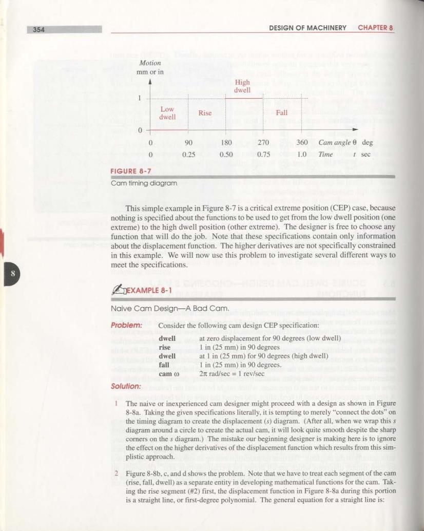
354 DESIGN OF MACHINERY CHAPTER 8 Motion mm or in High dwell Low dwell Rise Fall 0 0 90 180 270 360 Cam angle B deg 0 0.25 0.50 0.75 1.0 Time t sec FIGURE 8-7 Cam timing diagram This simple example in Figure 8-7 is a critical extreme position(CEP)case,because nothing is specified about the functions to be used to get from the low dwell position (one extreme)to the high dwell position(other extreme).The designer is free to choose any function that will do the job.Note that these specifications contain only information about the displacement function.The higher derivatives are not specifically constrained in this example.We will now use this problem to investigate several different ways to meet the specifications. EXAMPLE 8-1 Naive Cam Design-A Bad Cam. Problem: Consider the following cam design CEP specification: dwell at zero displacement for 90 degrees (low dwell) rise 1 in(25 mm)in 90 degrees dwell at 1 in(25 mm)for 90 degrees (high dwell) fall I in (25 mm)in 90 degrees. cam o 2n rad/sec 1 rev/sec Solution: 1 The naive or inexperienced cam designer might proceed with a design as shown in Figure 8-8a.Taking the given specifications literally,it is tempting to merely "connect the dots"on the timing diagram to create the displacement(s)diagram.(After all,when we wrap this s diagram around a circle to create the actual cam,it will look quite smooth despite the sharp comners on the s diagram.)The mistake our beginning designer is making here is to ignore the effect on the higher derivatives of the displacement function which results from this sim- plistic approach. 2 Figure 8-8b.c,and d shows the problem.Note that we have to treat each segment of the cam (rise,fall.dwell)as a separate entity in developing mathematical functions for the cam.Tak- ing the rise segment(#2)first,the displacement function in Figure 8-8a during this portion is a straight line,or first-degree polynomial.The general equation for a straight line is: