正在加载图片...

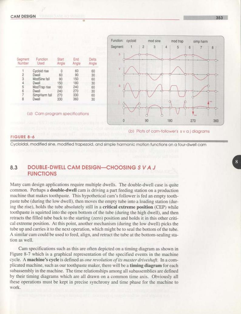
CAM DESIGN 353■ Function:cycloid mod sine mod trap simp harm Segment: 1 2 3 4 5 6 个 8 Segment Function Start End Delta Number Used Angle Angle Angle Cycloid rise 0 Dwell 90 ModSine fall 90 1 60 Dwell 150 180 ModTrap rise 180 240 6 Dwell 240 270 SimpHarm fall 270 330 0509050 8 Dwell 330 360 0 (a)Cam program specifications 180 270 360 (b)Plots of cam-follower's s v aj diagrams FIGURE 8-6 Cycloldal,modified sine,modified trapezoid,and simple harmonic motion functions on a four-dwell cam 8 8.3 DOUBLE-DWELL CAM DESIGN-CHOOSING S VAJ FUNCTIONS Many cam design applications require multiple dwells.The double-dwell case is quite common.Perhaps a double-dwell cam is driving a part feeding station on a production machine that makes toothpaste.This hypothetical cam's follower is fed an empty tooth- paste tube(during the low dwell),then moves the empty tube into a loading station(dur- ing the rise),holds the tube absolutely still in a critical extreme position(CEP)while toothpaste is squirted into the open bottom of the tube(during the high dwell),and then retracts the filled tube back to the starting(zero)position and holds it in this other criti- cal extreme position.At this point,another mechanism(during the low dwell)picks the tube up and carries it to the next operation,which might be to seal the bottom of the tube. A similar cam could be used to feed,align,and retract the tube at the bottom-sealing sta- tion as well. Cam specifications such as this are often depicted on a timing diagram as shown in Figure 8-7 which is a graphical representation of the specified events in the machine cycle.A machine's cycle is defined as one revolution of its master driveshaft.In a com- plicated machine,such as our toothpaste maker,there will be a timing diagram for each subassembly in the machine.The time relationships among all subassemblies are defined by their timing diagrams which are all drawn on a common time axis.Obviously all these operations must be kept in precise synchrony and time phase for the machine to work