正在加载图片...

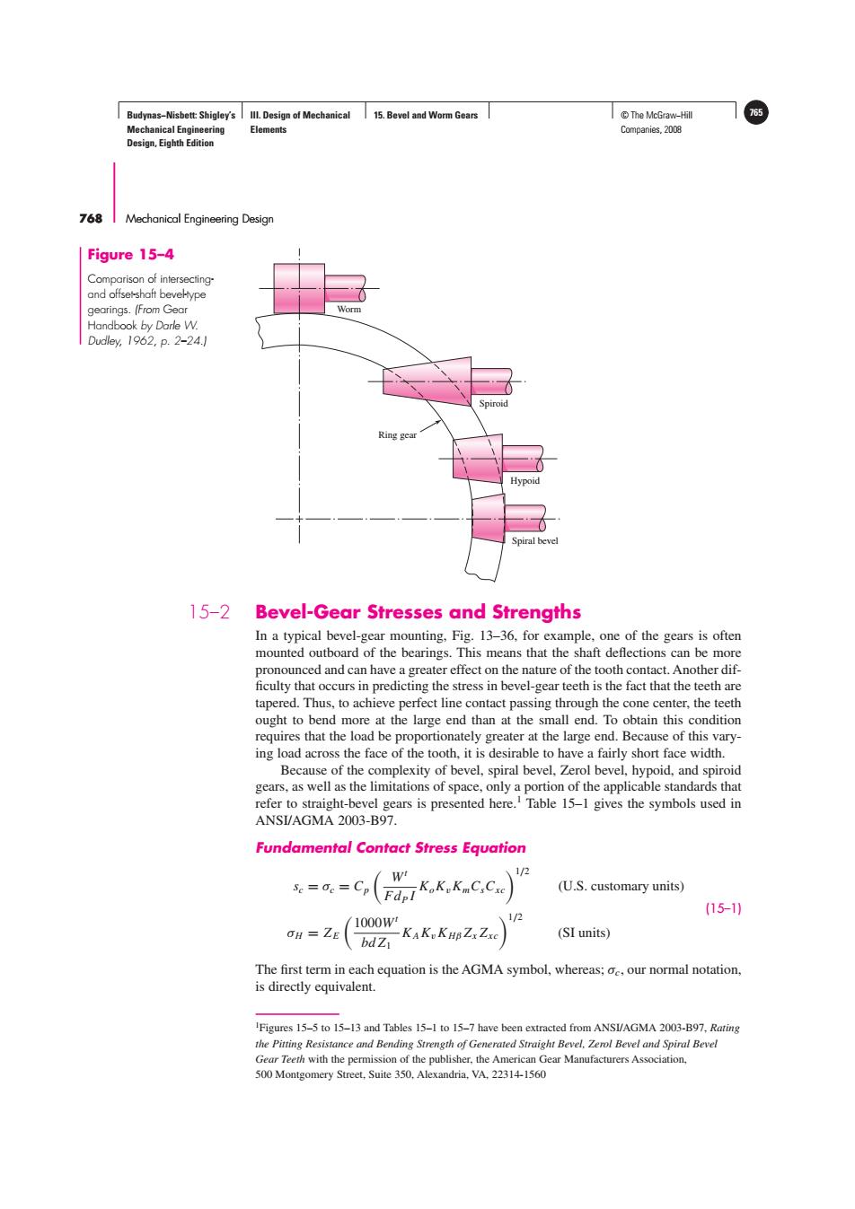
Budynas-Nisbett:Shigley's Ill.Design of Mechanical 15.Bevel and Worm Gears T©The McGraw-Hil 765 Mechanical Engineering Elements Companies,2008 Design,Eighth Edition 768 Mechanical Engineering Design Figure 15-4 Comparison of intersecting and offset-shoft beveHtype gearings.(From Gear Handbook by Darle W. Dudley,1962,p.2-24.] Spiroid Ring gear Hypoid Spiral bevel 15-2 Bevel-Gear Stresses and Strengths In a typical bevel-gear mounting,Fig.13-36.for example,one of the gears is often mounted outboard of the bearings.This means that the shaft deflections can be more pronounced and can have a greater effect on the nature of the tooth contact.Another dif- ficulty that occurs in predicting the stress in bevel-gear teeth is the fact that the teeth are tapered.Thus,to achieve perfect line contact passing through the cone center,the teeth ought to bend more at the large end than at the small end.To obtain this condition requires that the load be proportionately greater at the large end.Because of this vary- ing load across the face of the tooth,it is desirable to have a fairly short face width. Because of the complexity of bevel,spiral bevel,Zerol bevel,hypoid,and spiroid gears,as well as the limitations of space,only a portion of the applicable standards that refer to straight-bevel gears is presented here.Table 15-1 gives the symbols used in ANSI/AGMA 2003-B97. Fundamental Contact Stress Equation W 1/2 Se=0e=Cp :KoKKmCsCxe (U.S.customary units) (15-1) 1000W 1/2 OH ZE bdZy KAK KHBZxZxe (SI units) The first term in each equation is the AGMA symbol,whereas;oc,our normal notation, is directly equivalent. Figures 15-5 to 15-13 and Tables 15-1 to 15-7 have been extracted from ANSI/AGMA 2003-B97,Rating the Pitting Resistance and Bending Strength of Generated Straight Bevel.Zerol Bevel and Spiral Bevel Gear Teeth with the permission of the publisher,the American Gear Manufacturers Association, 500 Montgomery Street,Suite 350.Alexandria,VA,22314-1560Budynas−Nisbett: Shigley’s Mechanical Engineering Design, Eighth Edition III. Design of Mechanical Elements 15. Bevel and Worm Gears © The McGraw−Hill 765 Companies, 2008 768 Mechanical Engineering Design Worm Spiroid Hypoid Spiral bevel Ring gear Figure 15–4 Comparison of intersectingand offset-shaft bevel-type gearings. (From Gear Handbook by Darle W. Dudley, 1962, p. 2–24.) 15–2 Bevel-Gear Stresses and Strengths In a typical bevel-gear mounting, Fig. 13–36, for example, one of the gears is often mounted outboard of the bearings. This means that the shaft deflections can be more pronounced and can have a greater effect on the nature of the tooth contact. Another dif- ficulty that occurs in predicting the stress in bevel-gear teeth is the fact that the teeth are tapered. Thus, to achieve perfect line contact passing through the cone center, the teeth ought to bend more at the large end than at the small end. To obtain this condition requires that the load be proportionately greater at the large end. Because of this varying load across the face of the tooth, it is desirable to have a fairly short face width. Because of the complexity of bevel, spiral bevel, Zerol bevel, hypoid, and spiroid gears, as well as the limitations of space, only a portion of the applicable standards that refer to straight-bevel gears is presented here.1 Table 15–1 gives the symbols used in ANSI/AGMA 2003-B97. Fundamental Contact Stress Equation sc = σc = Cp Wt FdP I KoKvKmCsCxc1/2 (U.S. customary units) σH = Z E 1000Wt bd Z1 KAKvK Hβ Zx Zxc1/2 (SI units) (15–1) The first term in each equation is the AGMA symbol, whereas; σc, our normal notation, is directly equivalent. 1 Figures 15–5 to 15–13 and Tables 15–1 to 15–7 have been extracted from ANSI/AGMA 2003-B97, Rating the Pitting Resistance and Bending Strength of Generated Straight Bevel, Zerol Bevel and Spiral Bevel Gear Teeth with the permission of the publisher, the American Gear Manufacturers Association, 500 Montgomery Street, Suite 350, Alexandria, VA, 22314-1560����