正在加载图片...

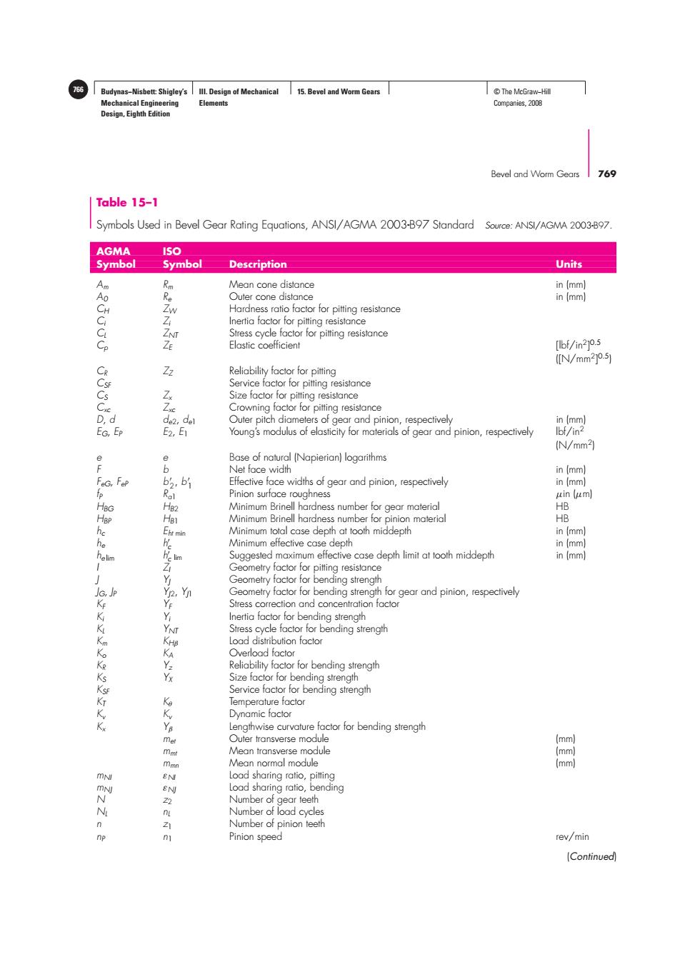
766 Budynas-Nisbett:Shigley's Ill.Design of Mechanical 15.Bevel and Worm Gears ©The McGraw-Hill Mechanical Engineering Elements Companies,2008 Design,Eighth Edition Bevel and Worm Gears 769 Table 15-1 Symbols Used in Bevel Gear Rating Equations,ANSI/AGMA 2003-B97 Standard Source:ANSI/AGMA 2003-B97 AGMA ISO Symbol Symbol Description Units Mean cone distance in (mm) Outer cone distance in (mm) Hardness ratio factor for pitting resistance Inertia factor for pitting resistance Stress cycle factor for pitting resistance Elastic coefficient [bf/in2]0.5 N/mm2°.) 3 Reliability factor for pitting Service factor for pitting resistance Size factor for pitting resistance Crowning factor for pitting resistance d de2,del Outer pitch diameters of gear and pinion,respectively in (mm) Ep E2,E1 Young's modulus of elasticity for materials of gear and pinion,respectively Ibf/in2 (N/mm2) Base of natural (Napierian)logarithms Net face width in (mm) 8 b2 b1 Effective face widths of gear and pinion,respectively in (mm) ⊙ Pinion surface roughness uin (um] Minimum Brinell hardness number for gear material HB HB1 Minimum Brinell hardness number for pinion material HB Eht min Minimum total case depth at tooth middepth in (mm) 云 Minimum effective case depth in (mm lim Suggested maximum effective case depth limit at tooth middepth in (mm) Geometry factor for pitting resistance Geometry factor for bending strength Geometry factor for bending strength for gear and pinion,respectively Stress correction and concentration factor Inertia factor for bending strength Y Stress cycle factor for bending strength KHB Load distribution factor Overload factor Reliability factor for bending strength Size factor for bending strength Service factor for bending strength Temperature factor Dynamic factor Lengthwise curvature factor for bending strength met Outer transverse module (mm) mmt Mean transverse module (mm) mn Mean normal module (mm) mN Load sharing ratio,pitting EN Load sharing ratio,bending Number of gear teeth Number of load cycles 21 Number of pinion teeth Pinion speed ev/min ContinuedBudynas−Nisbett: Shigley’s Mechanical Engineering Design, Eighth Edition III. Design of Mechanical Elements 15. Bevel and Worm Gears 766 © The McGraw−Hill Companies, 2008 Bevel and Worm Gears 769 Table 15–1 Symbols Used in Bevel Gear Rating Equations, ANSI/AGMA 2003-B97 Standard Source: ANSI/AGMA 2003-B97. AGMA ISO Symbol Symbol Description Units Am Rm Mean cone distance in (mm) A0 Re Outer cone distance in (mm) CH ZW Hardness ratio factor for pitting resistance Ci Zi Inertia factor for pitting resistance CL ZNT Stress cycle factor for pitting resistance Cp ZE Elastic coefficient [lbf/in2] 0.5 ([N/mm2] 0.5) CR ZZ Reliability factor for pitting CSF Service factor for pitting resistance CS Zx Size factor for pitting resistance Cxc Zxc Crowning factor for pitting resistance D, d de2, de1 Outer pitch diameters of gear and pinion, respectively in (mm) EG, EP E2, E1 Young’s modulus of elasticity for materials of gear and pinion, respectively lbf/in2 (N/mm2) e e Base of natural (Napierian) logarithms F b Net face width in (mm) FeG, FeP b 2, b 1 Effective face widths of gear and pinion, respectively in (mm) fP Ra1 Pinion surface roughness μin (μm) HBG HB2 Minimum Brinell hardness number for gear material HB HBP HB1 Minimum Brinell hardness number for pinion material HB hc Eht min Minimum total case depth at tooth middepth in (mm) he h c Minimum effective case depth in (mm) he lim h c lim Suggested maximum effective case depth limit at tooth middepth in (mm) I ZI Geometry factor for pitting resistance J YJ Geometry factor for bending strength JG, JP YJ2, YJ1 Geometry factor for bending strength for gear and pinion, respectively KF YF Stress correction and concentration factor Ki Yi Inertia factor for bending strength KL YNT Stress cycle factor for bending strength Km KHβ Load distribution factor Ko KA Overload factor KR Yz Reliability factor for bending strength KS YX Size factor for bending strength KSF Service factor for bending strength KT Kθ Temperature factor Kv Kv Dynamic factor Kx Yβ Lengthwise curvature factor for bending strength met Outer transverse module (mm) mmt Mean transverse module (mm) mmn Mean normal module (mm) mNI εNI Load sharing ratio, pitting mNJ εNJ Load sharing ratio, bending N z2 Number of gear teeth NL nL Number of load cycles n z1 Number of pinion teeth nP n1 Pinion speed rev/min (Continued)����