正在加载图片...
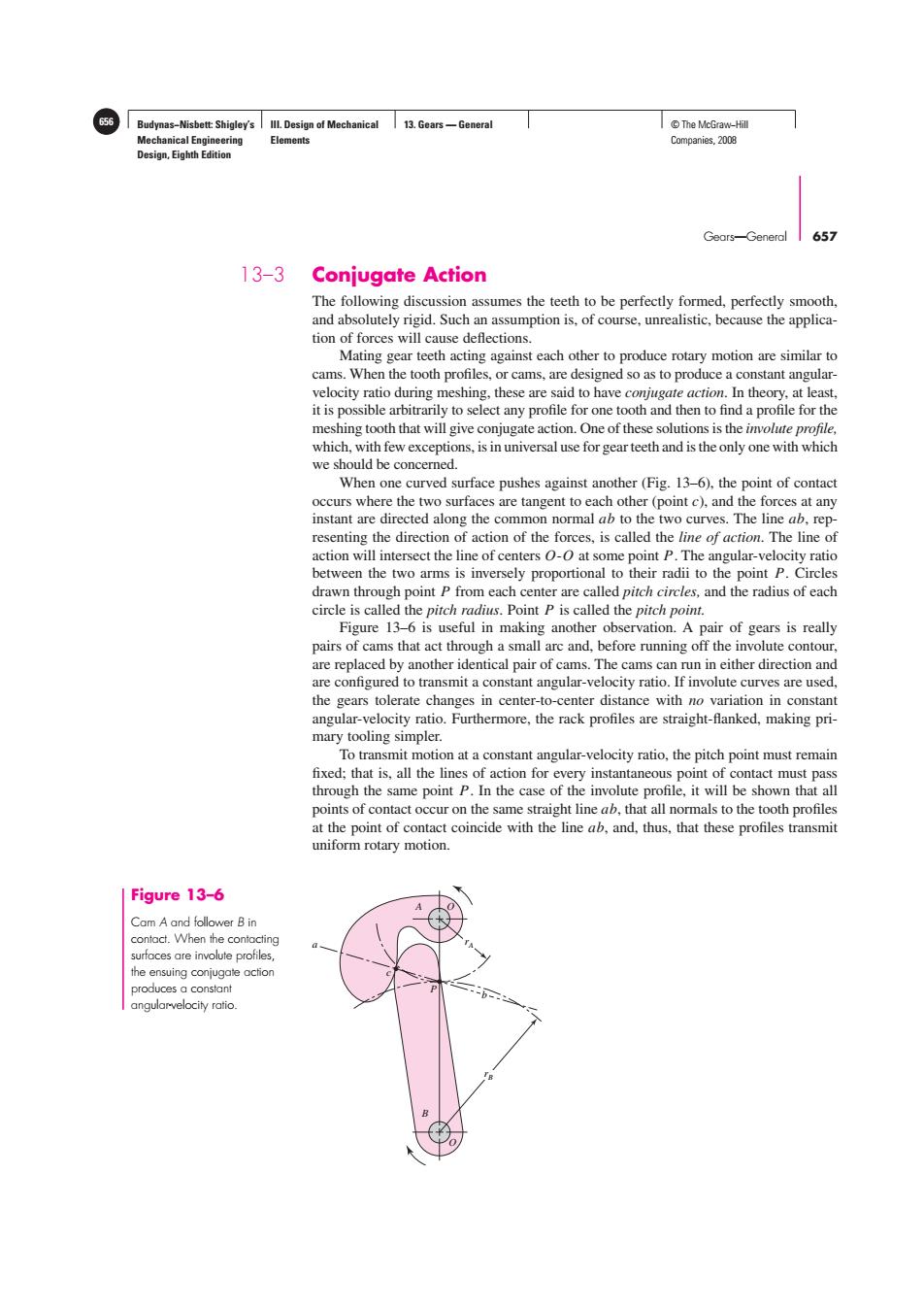
656 Budynas-Nisbett Shigley's IIl Design of Mechanical 13.Gears-General T©The McGraw-Hil Mechanical Engineering Elements Companies,2008 Design,Eighth Edition Gears-General 657 13-3 Conjugate Action The following discussion assumes the teeth to be perfectly formed,perfectly smooth, and absolutely rigid.Such an assumption is,of course,unrealistic,because the applica- tion of forces will cause deflections. Mating gear teeth acting against each other to produce rotary motion are similar to cams.When the tooth profiles,or cams,are designed so as to produce a constant angular- velocity ratio during meshing,these are said to have conjugate action.In theory,at least, it is possible arbitrarily to select any profile for one tooth and then to find a profile for the meshing tooth that will give conjugate action.One of these solutions is the imolute profile, which,with few exceptions,is in universal use for gear teeth and is the only one with which we should be concerned. When one curved surface pushes against another(Fig.13-6),the point of contact occurs where the two surfaces are tangent to each other(point c),and the forces at any instant are directed along the common normal ab to the two curves.The line ab,rep- resenting the direction of action of the forces,is called the line of action.The line of action will intersect the line of centers O-0 at some point P.The angular-velocity ratio between the two arms is inversely proportional to their radii to the point P.Circles drawn through point P from each center are called pitch circles,and the radius of each circle is called the pitch radius.Point P is called the pitch point. Figure 13-6 is useful in making another observation.A pair of gears is really pairs of cams that act through a small arc and,before running off the involute contour, are replaced by another identical pair of cams.The cams can run in either direction and are configured to transmit a constant angular-velocity ratio.If involute curves are used, the gears tolerate changes in center-to-center distance with no variation in constant angular-velocity ratio.Furthermore,the rack profiles are straight-fanked,making pri- mary tooling simpler. To transmit motion at a constant angular-velocity ratio,the pitch point must remain fixed;that is,all the lines of action for every instantaneous point of contact must pass through the same point P.In the case of the involute profile,it will be shown that all points of contact occur on the same straight line ab,that all normals to the tooth profiles at the point of contact coincide with the line ab,and,thus,that these profiles transmit uniform rotary motion. Figure 13-6 Cam A and follower B in contact.When the contacting surfaces are involute profiles the ensuing conjugate action produces a constant angularvelocity ratioBudynas−Nisbett: Shigley’s Mechanical Engineering Design, Eighth Edition III. Design of Mechanical Elements 13. Gears — General 656 © The McGraw−Hill Companies, 2008 Gears—General 657 O B rB rA b c a A O P Figure 13–6 Cam A and follower B in contact. When the contacting surfaces are involute profiles, the ensuing conjugate action produces a constant angular-velocity ratio. 13–3 Conjugate Action The following discussion assumes the teeth to be perfectly formed, perfectly smooth, and absolutely rigid. Such an assumption is, of course, unrealistic, because the application of forces will cause deflections. Mating gear teeth acting against each other to produce rotary motion are similar to cams. When the tooth profiles, or cams, are designed so as to produce a constant angularvelocity ratio during meshing, these are said to have conjugate action. In theory, at least, it is possible arbitrarily to select any profile for one tooth and then to find a profile for the meshing tooth that will give conjugate action. One of these solutions is the involute profile, which, with few exceptions, is in universal use for gear teeth and is the only one with which we should be concerned. When one curved surface pushes against another (Fig. 13–6), the point of contact occurs where the two surfaces are tangent to each other (point c), and the forces at any instant are directed along the common normal ab to the two curves. The line ab, representing the direction of action of the forces, is called the line of action. The line of action will intersect the line of centers O-O at some point P. The angular-velocity ratio between the two arms is inversely proportional to their radii to the point P. Circles drawn through point P from each center are called pitch circles, and the radius of each circle is called the pitch radius. Point P is called the pitch point. Figure 13–6 is useful in making another observation. A pair of gears is really pairs of cams that act through a small arc and, before running off the involute contour, are replaced by another identical pair of cams. The cams can run in either direction and are configured to transmit a constant angular-velocity ratio. If involute curves are used, the gears tolerate changes in center-to-center distance with no variation in constant angular-velocity ratio. Furthermore, the rack profiles are straight-flanked, making primary tooling simpler. To transmit motion at a constant angular-velocity ratio, the pitch point must remain fixed; that is, all the lines of action for every instantaneous point of contact must pass through the same point P. In the case of the involute profile, it will be shown that all points of contact occur on the same straight line ab, that all normals to the tooth profiles at the point of contact coincide with the line ab, and, thus, that these profiles transmit uniform rotary motion