正在加载图片...
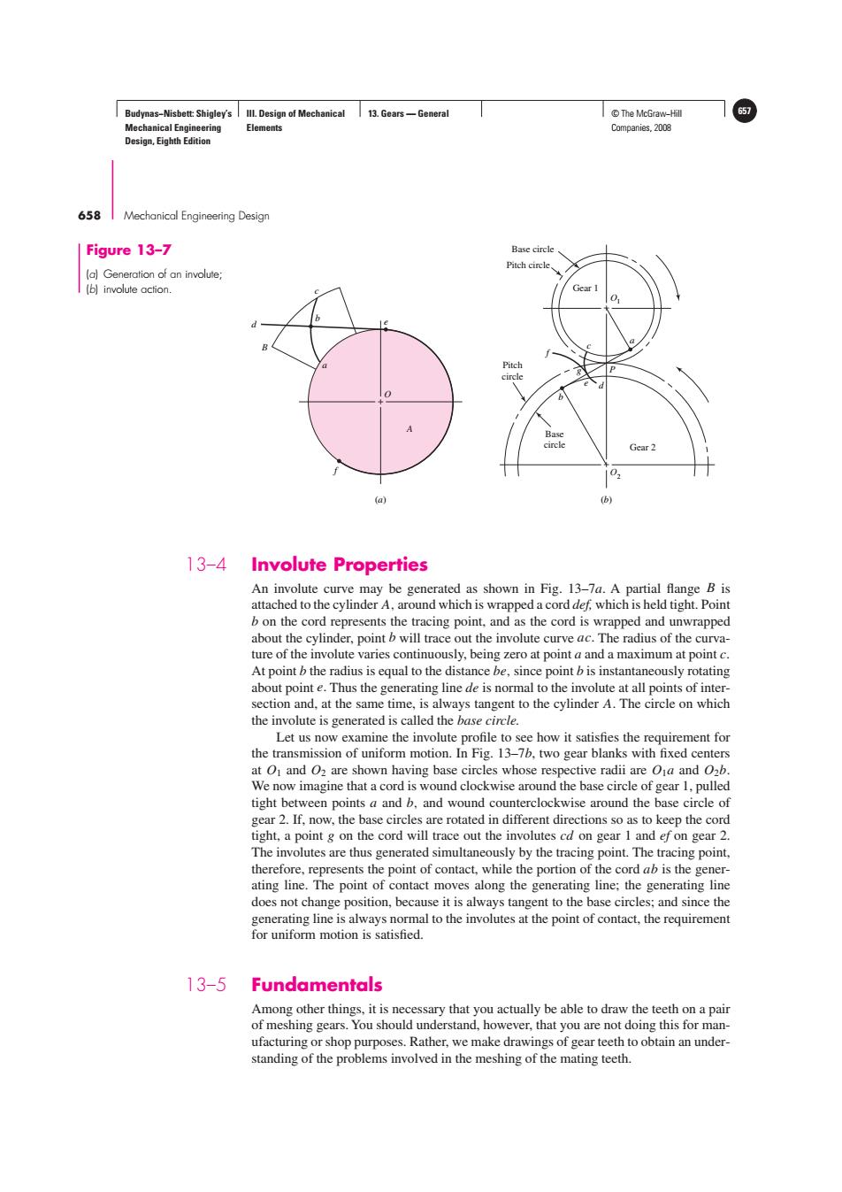
Budynas-Nisbett:Shigley's Ill.Design of Mechanical 13.Gears-General T©The McGraw-Hil Mechanical Engineering Elements Companies,2008 Design,Eighth Edition 658 Mechanical Engineering Design Figure 13-7 Base circle Pitch circle (a)Generation of an involute; (b)involute action. Gear I Pitch circle Base cirele Gear 2 102 (a) (b) 13-4 Involute Properties An involute curve may be generated as shown in Fig.13-7a.A partial flange B is attached to the cylinder A,around which is wrapped a cord def,which is held tight.Point b on the cord represents the tracing point.and as the cord is wrapped and unwrapped about the cylinder,point b will trace out the involute curve ac.The radius of the curva- ture of the involute varies continuously,being zero at point a and a maximum at point c. At point b the radius is equal to the distance be,since point b is instantaneously rotating about point e.Thus the generating line de is normal to the involute at all points of inter- section and,at the same time,is always tangent to the cylinder A.The circle on which the involute is generated is called the base circle. Let us now examine the involute profile to see how it satisfies the requirement for the transmission of uniform motion.In Fig.13-7b,two gear blanks with fixed centers at O1 and O2 are shown having base circles whose respective radii are Oja and O2b. We now imagine that a cord is wound clockwise around the base circle of gear 1,pulled tight between points a and b,and wound counterclockwise around the base circle of gear 2.If,now,the base circles are rotated in different directions so as to keep the cord tight,a point g on the cord will trace out the involutes cd on gear 1 and ef on gear 2. The involutes are thus generated simultaneously by the tracing point.The tracing point, therefore,represents the point of contact,while the portion of the cord ab is the gener- ating line.The point of contact moves along the generating line;the generating line does not change position,because it is always tangent to the base circles;and since the generating line is always normal to the involutes at the point of contact,the requirement for uniform motion is satisfied. 13-5 Fundamentals Among other things,it is necessary that you actually be able to draw the teeth on a pair of meshing gears.You should understand,however,that you are not doing this for man- ufacturing or shop purposes.Rather,we make drawings of gear teeth to obtain an under- standing of the problems involved in the meshing of the mating teeth.Budynas−Nisbett: Shigley’s Mechanical Engineering Design, Eighth Edition III. Design of Mechanical Elements 13. Gears — General © The McGraw−Hill 657 Companies, 2008 658 Mechanical Engineering Design + + + Base circle Pitch circle O1 O2 c a P e d g f b d B b c e a A O f Pitch circle Gear 1 Gear 2 Base circle (a) (b) Figure 13–7 (a) Generation of an involute; (b) involute action. 13–4 Involute Properties An involute curve may be generated as shown in Fig. 13–7a. A partial flange B is attached to the cylinder A, around which is wrapped a cord def, which is held tight. Point b on the cord represents the tracing point, and as the cord is wrapped and unwrapped about the cylinder, point b will trace out the involute curve ac. The radius of the curvature of the involute varies continuously, being zero at point a and a maximum at point c. At point b the radius is equal to the distance be, since point b is instantaneously rotating about point e. Thus the generating line de is normal to the involute at all points of intersection and, at the same time, is always tangent to the cylinder A. The circle on which the involute is generated is called the base circle. Let us now examine the involute profile to see how it satisfies the requirement for the transmission of uniform motion. In Fig. 13–7b, two gear blanks with fixed centers at O1 and O2 are shown having base circles whose respective radii are O1a and O2b. We now imagine that a cord is wound clockwise around the base circle of gear 1, pulled tight between points a and b, and wound counterclockwise around the base circle of gear 2. If, now, the base circles are rotated in different directions so as to keep the cord tight, a point g on the cord will trace out the involutes cd on gear 1 and ef on gear 2. The involutes are thus generated simultaneously by the tracing point. The tracing point, therefore, represents the point of contact, while the portion of the cord ab is the generating line. The point of contact moves along the generating line; the generating line does not change position, because it is always tangent to the base circles; and since the generating line is always normal to the involutes at the point of contact, the requirement for uniform motion is satisfied. 13–5 Fundamentals Among other things, it is necessary that you actually be able to draw the teeth on a pair of meshing gears. You should understand, however, that you are not doing this for manufacturing or shop purposes. Rather, we make drawings of gear teeth to obtain an understanding of the problems involved in the meshing of the mating teeth