正在加载图片...
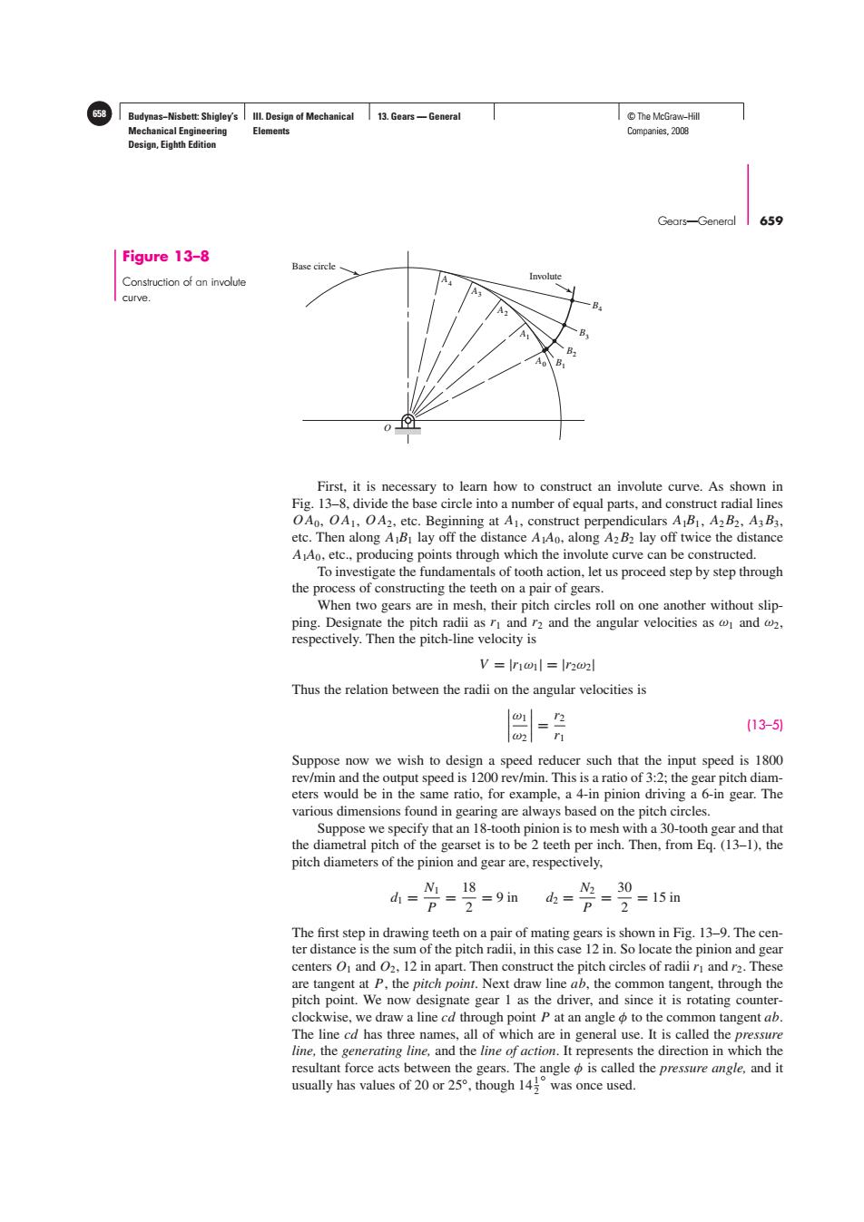
58 Budynas-Nisbett:Shigley's Ill.Design of Mechanical 13.Gears-General T©The McGraw-Hil Mechanical Engineering Elements Companies,2008 Design,Eighth Edition Gears-General 659 Figure 13-8 Base circle Construction of an involute Involute curve. 0- First,it is necessary to learn how to construct an involute curve.As shown in Fig.13-8,divide the base circle into a number of equal parts,and construct radial lines OAo.OA1,OA2,etc.Beginning at A1,construct perpendiculars A BI,A2B2,A3 B3. etc.Then along A B lay off the distance A Ao,along A2B2 lay off twice the distance A Ao,etc.,producing points through which the involute curve can be constructed. To investigate the fundamentals of tooth action,let us proceed step by step through the process of constructing the teeth on a pair of gears. When two gears are in mesh,their pitch circles roll on one another without slip- ping.Designate the pitch radii as r and r2 and the angular velocities as and 2, respectively.Then the pitch-line velocity is V Ir1oil Ir2o2l Thus the relation between the radii on the angular velocities is (13-5) r Suppose now we wish to design a speed reducer such that the input speed is 1800 rev/min and the output speed is 1200 rev/min.This is a ratio of 3:2;the gear pitch diam- eters would be in the same ratio,for example,a 4-in pinion driving a 6-in gear.The various dimensions found in gearing are always based on the pitch circles. Suppose we specify that an 18-tooth pinion is to mesh with a 30-tooth gear and that the diametral pitch of the gearset is to be 2 teeth per inch.Then,from Eq.(13-1).the pitch diameters of the pinion and gear are,respectively, N118 N230 d= p=2=9in d2= p=2=15im The first step in drawing teeth on a pair of mating gears is shown in Fig.13-9.The cen- ter distance is the sum of the pitch radii,in this case 12 in.So locate the pinion and gear centers O and 02,12 in apart.Then construct the pitch circles of radii r and r2.These are tangent at P,the pitch point.Next draw line ab,the common tangent,through the pitch point.We now designate gear 1 as the driver,and since it is rotating counter- clockwise,we draw a line cd through point P at an angle to the common tangent ab. The line cd has three names,all of which are in general use.It is called the pressure line,the generating line,and the line of action.It represents the direction in which the resultant force acts between the gears.The angle is called the pressure angle,and it usually has values of20or25°,thoughI4°was once used..Budynas−Nisbett: Shigley’s Mechanical Engineering Design, Eighth Edition III. Design of Mechanical Elements 13. Gears — General 658 © The McGraw−Hill Companies, 2008 Gears—General 659 O Base circle Involute A4 A3 A2 A1 A0 B1 B2 B3 B4 Figure 13–8 Construction of an involute curve. First, it is necessary to learn how to construct an involute curve. As shown in Fig. 13–8, divide the base circle into a number of equal parts, and construct radial lines O A0, O A1, O A2, etc. Beginning at A1, construct perpendiculars A1B1, A2B2, A3B3, etc. Then along A1B1 lay off the distance A1A0, along A2B2 lay off twice the distance A1A0, etc., producing points through which the involute curve can be constructed. To investigate the fundamentals of tooth action, let us proceed step by step through the process of constructing the teeth on a pair of gears. When two gears are in mesh, their pitch circles roll on one another without slipping. Designate the pitch radii as r1 and r2 and the angular velocities as ω1 and ω2, respectively. Then the pitch-line velocity is V = |r1ω1| = |r2ω2| Thus the relation between the radii on the angular velocities is ω1 ω2 = r2 r1 (13–5) Suppose now we wish to design a speed reducer such that the input speed is 1800 rev/min and the output speed is 1200 rev/min. This is a ratio of 3:2; the gear pitch diameters would be in the same ratio, for example, a 4-in pinion driving a 6-in gear. The various dimensions found in gearing are always based on the pitch circles. Suppose we specify that an 18-tooth pinion is to mesh with a 30-tooth gear and that the diametral pitch of the gearset is to be 2 teeth per inch. Then, from Eq. (13–1), the pitch diameters of the pinion and gear are, respectively, d1 = N1 P = 18 2 = 9 in d2 = N2 P = 30 2 = 15 in The first step in drawing teeth on a pair of mating gears is shown in Fig. 13–9. The center distance is the sum of the pitch radii, in this case 12 in. So locate the pinion and gear centers O1 and O2, 12 in apart. Then construct the pitch circles of radii r1 and r2. These are tangent at P, the pitch point. Next draw line ab, the common tangent, through the pitch point. We now designate gear 1 as the driver, and since it is rotating counterclockwise, we draw a line cd through point P at an angle φ to the common tangent ab. The line cd has three names, all of which are in general use. It is called the pressure line, the generating line, and the line of action. It represents the direction in which the resultant force acts between the gears. The angle φ is called the pressure angle, and it usually has values of 20 or 25◦, though 141 2 ◦ was once used.��������