正在加载图片...

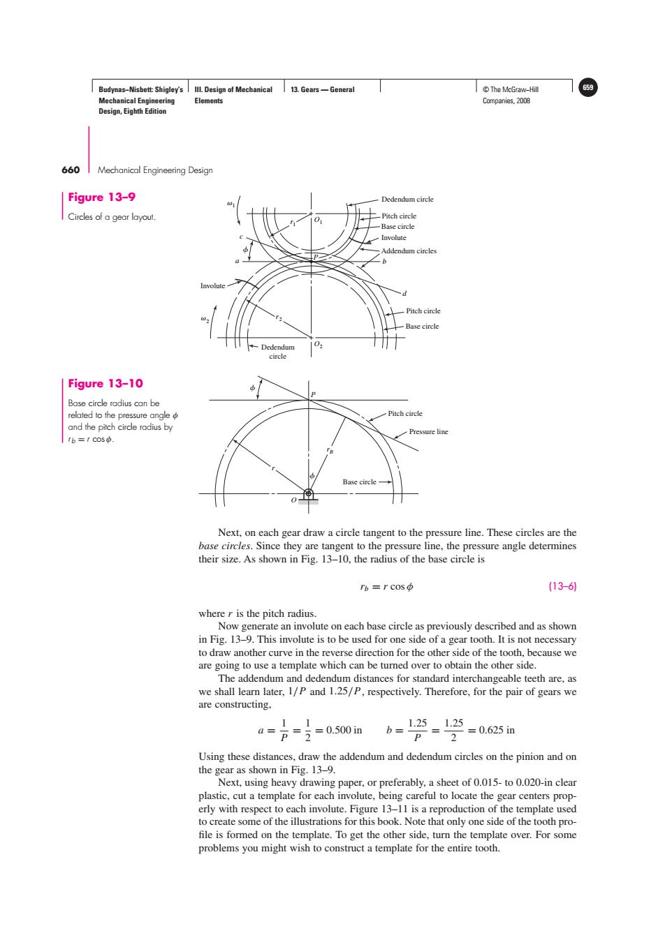
Budynas-Nisbett:Shigley's Ill.Design of Mechanical 13.Gears-General T©The McGraw-Hill 659 Mechanical Engineering Elements Companies,2008 Design,Eighth Edition 660 Mechanical Engineering Design Figure 13-9 Dedendum circle Circles of a gear layout -Pitch circle Base circle Involute Addendum circles Pitch circle Base circle -Dedendum circle Figure 13-10 Base circle radius can be related to the pressure angle Pitch circle and the pitch circle rodius by Pressure line rb=rCos中. Base circle Next,on each gear draw a circle tangent to the pressure line.These circles are the base circles.Since they are tangent to the pressure line,the pressure angle determines their size.As shown in Fig.13-10,the radius of the base circle is rb=rCos中 (13-61 where r is the pitch radius. Now generate an involute on each base circle as previously described and as shown in Fig.13-9.This involute is to be used for one side of a gear tooth.It is not necessary to draw another curve in the reverse direction for the other side of the tooth,because we are going to use a template which can be turned over to obtain the other side. The addendum and dedendum distances for standard interchangeable teeth are,as we shall learn later,1/P and 1.25/P,respectively.Therefore,for the pair of gears we are constructing, 11 4= p=i=0.500in b=12=1空=065n P Using these distances,draw the addendum and dedendum circles on the pinion and on the gear as shown in Fig.13-9. Next,using heavy drawing paper,or preferably,a sheet of 0.015-to 0.020-in clear plastic,cut a template for each involute,being careful to locate the gear centers prop- erly with respect to each involute.Figure 13-11 is a reproduction of the template used to create some of the illustrations for this book.Note that only one side of the tooth pro- file is formed on the template.To get the other side,turn the template over.For some problems you might wish to construct a template for the entire tooth.Budynas−Nisbett: Shigley’s Mechanical Engineering Design, Eighth Edition III. Design of Mechanical Elements 13. Gears — General © The McGraw−Hill 659 Companies, 2008 660 Mechanical Engineering Design O r P Pitch circle Pressure line Base circle rB Figure 13–10 Base circle radius can be related to the pressure angle φ and the pitch circle radius by r b = r cos φ. Next, on each gear draw a circle tangent to the pressure line. These circles are the base circles. Since they are tangent to the pressure line, the pressure angle determines their size. As shown in Fig. 13–10, the radius of the base circle is rb = r cos φ (13–6) where r is the pitch radius. Now generate an involute on each base circle as previously described and as shown in Fig. 13–9. This involute is to be used for one side of a gear tooth. It is not necessary to draw another curve in the reverse direction for the other side of the tooth, because we are going to use a template which can be turned over to obtain the other side. The addendum and dedendum distances for standard interchangeable teeth are, as we shall learn later, 1/P and 1.25/P, respectively. Therefore, for the pair of gears we are constructing, a = 1 P = 1 2 = 0.500 in b = 1.25 P = 1.25 2 = 0.625 in Using these distances, draw the addendum and dedendum circles on the pinion and on the gear as shown in Fig. 13–9. Next, using heavy drawing paper, or preferably, a sheet of 0.015- to 0.020-in clear plastic, cut a template for each involute, being careful to locate the gear centers properly with respect to each involute. Figure 13–11 is a reproduction of the template used to create some of the illustrations for this book. Note that only one side of the tooth pro- file is formed on the template. To get the other side, turn the template over. For some problems you might wish to construct a template for the entire tooth. Base circle + + Dedendum circle Pitch circle Base circle Involute Addendum circles Pitch circle b d a c P O1 O2 r1 r2 Dedendum circle Involute 1 2 Figure 13–9 Circles of a gear layout. �����