正在加载图片...
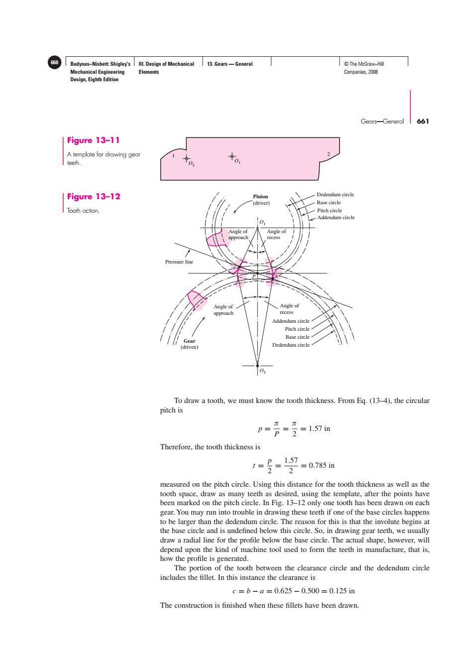
Budynas-Nisbett:Shigley's Ill.Design of Mechanical 13.Gears-General T©The McGraw-Hil Mechanical Engineering Elements Companies,2008 Design,Eighth Edition Gears-General 661 Figure 13-11 A template for drawing gear teeth. 女0 Figure 13-12 Pinion Dedendum circle (driver Base circle Tooth action. Pitch circle Addendum circle 0> Angle of Angle of Pressure Angle of Angle of approach recess Addendum circle Pitch circle Base circle Gear (driven) Dedendum circle 03 To draw a tooth,we must know the tooth thickness.From Eq.(13-4),the circular pitch is p=2=1.57in Therefore,the tooth thickness is =0.785in measured on the pitch circle.Using this distance for the tooth thickness as well as the tooth space,draw as many teeth as desired,using the template,after the points have been marked on the pitch circle.In Fig.13-12 only one tooth has been drawn on each gear.You may run into trouble in drawing these teeth if one of the base circles happens to be larger than the dedendum circle.The reason for this is that the involute begins at the base circle and is undefined below this circle.So,in drawing gear teeth,we usually draw a radial line for the profile below the base circle.The actual shape,however,will depend upon the kind of machine tool used to form the teeth in manufacture,that is, how the profile is generated. The portion of the tooth between the clearance circle and the dedendum circle includes the fillet.In this instance the clearance is c=b-a=0.625-0.500=0.125in The construction is finished when these fillets have been drawn.Budynas−Nisbett: Shigley’s Mechanical Engineering Design, Eighth Edition III. Design of Mechanical Elements 13. Gears — General 660 © The McGraw−Hill Companies, 2008 Gears—General 661 2 1 O2 O1 Figure 13–11 A template for drawing gear teeth. Angle of approach P Angle of recess O2 O1 Pressure line Dedendum circle Base circle Pitch circle Addendum circle Angle of recess Pinion (driver) Addendum circle Pitch circle Base circle Dedendum circle Gear (driven) a b Angle of approach Figure 13–12 Tooth action. To draw a tooth, we must know the tooth thickness. From Eq. (13–4), the circular pitch is p = π P = π 2 = 1.57 in Therefore, the tooth thickness is t = p 2 = 1.57 2 = 0.785 in measured on the pitch circle. Using this distance for the tooth thickness as well as the tooth space, draw as many teeth as desired, using the template, after the points have been marked on the pitch circle. In Fig. 13–12 only one tooth has been drawn on each gear. You may run into trouble in drawing these teeth if one of the base circles happens to be larger than the dedendum circle. The reason for this is that the involute begins at the base circle and is undefined below this circle. So, in drawing gear teeth, we usually draw a radial line for the profile below the base circle. The actual shape, however, will depend upon the kind of machine tool used to form the teeth in manufacture, that is, how the profile is generated. The portion of the tooth between the clearance circle and the dedendum circle includes the fillet. In this instance the clearance is c = b − a = 0.625 − 0.500 = 0.125 in The construction is finished when these fillets have been drawn