正在加载图片...

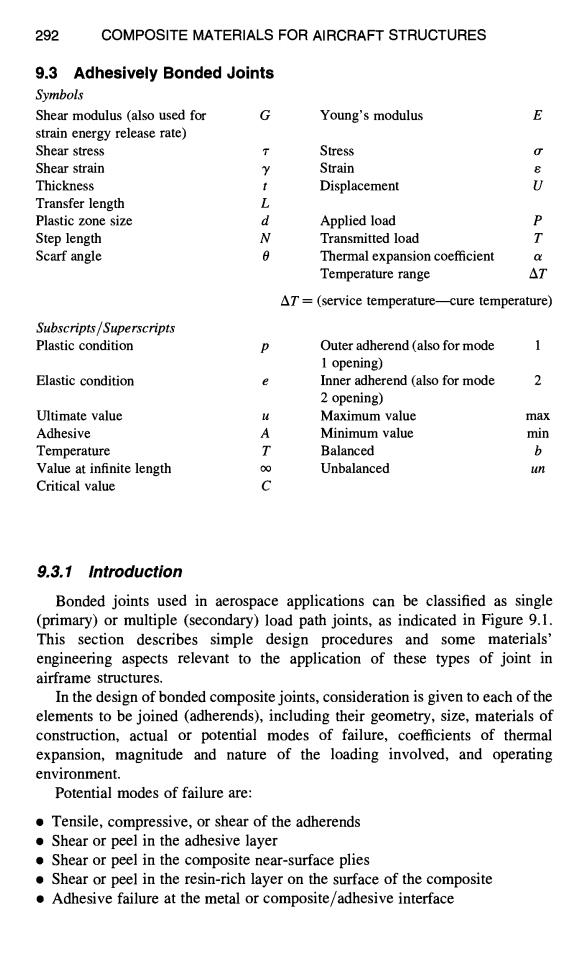
292 COMPOSITE MATERIALS FOR AIRCRAFT STRUCTURES 9.3 Adhesively Bonded Joints Symbols Shear modulus (also used for Young's modulus E strain energy release rate) Shear stress T Stress Shear strain Y Strain Thickness Displacement U Transfer length L Plastic zone size d Applied load P Step length N Transmitted load T Scarf angle Thermal expansion coefficient Temperature range △T AT=(service temperature-cure temperature) Subscripts/Superscripts Plastic condition Outer adherend (also for mode 1 opening) Elastic condition Inner adherend (also for mode 2 2 opening) Ultimate value Maximum value max Adhesive A Minimum value min Temperature T Balanced b Value at infinite length 0∞ Unbalanced un Critical value C 9.3.1 Introduction Bonded joints used in aerospace applications can be classified as single (primary)or multiple (secondary)load path joints,as indicated in Figure 9.1. This section describes simple design procedures and some materials' engineering aspects relevant to the application of these types of joint in airframe structures. In the design of bonded composite joints,consideration is given to each of the elements to be joined (adherends),including their geometry,size,materials of construction,actual or potential modes of failure,coefficients of thermal expansion,magnitude and nature of the loading involved,and operating environment. Potential modes of failure are: Tensile,compressive,or shear of the adherends Shear or peel in the adhesive layer .Shear or peel in the composite near-surface plies Shear or peel in the resin-rich layer on the surface of the composite Adhesive failure at the metal or composite/adhesive interface292 COMPOSITE MATERIALS FOR AIRCRAFT STRUCTURES 9,3 Adhesively Bonded Joints Symbols Shear modulus (also used for G strain energy release rate) Shear stress ~- Shear strain y Thickness t Transfer length L Plastic zone size d Step length N Scarf angle 0 Young' s modulus E Stress o" Strain e Displacement U Applied load P Transmitted load T Thermal expansion coefficient a Temperature range AT AT = (service temperature----cure temperature) Subscripts/Superscripts Plastic condition p Outer adherend (also for mode 1 1 opening) Elastic condition e Inner adherend (also for mode 2 2 opening) Ultimate value u Maximum value max Adhesive A Minimum value min Temperature T Balanced b Value at infinite length co Unbalanced un Critical value C 9.3.1 Introduction Bonded joints used in aerospace applications can be classified as single (primary) or multiple (secondary) load path joints, as indicated in Figure 9.1. This section describes simple design procedures and some materials' engineering aspects relevant to the application of these types of joint in airframe structures. In the design of bonded composite joints, consideration is given to each of the elements to be joined (adherends), including their geometry, size, materials of construction, actual or potential modes of failure, coefficients of thermal expansion, magnitude and nature of the loading involved, and operating environment. Potential modes of failure are: • Tensile, compressive, or shear of the adherends • Shear or peel in the adhesive layer • Shear or peel in the composite near-surface plies • Shear or peel in the resin-rich layer on the surface of the composite • Adhesive failure at the metal or composite/adhesive interface