正在加载图片...
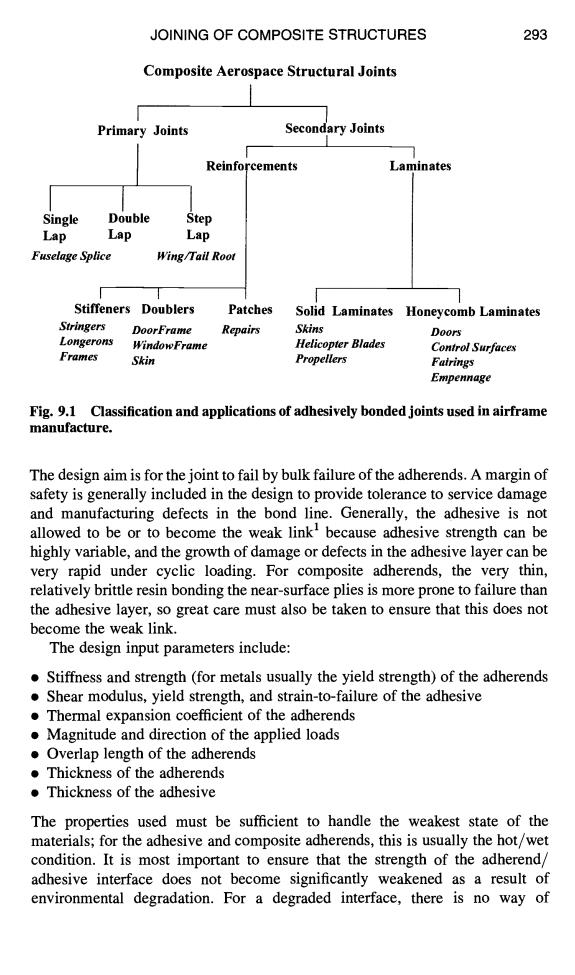
JOINING OF COMPOSITE STRUCTURES 293 Composite Aerospace Structural Joints Primary Joints Secondary Joints Reinforcements Laminates Single Double Step Lap Lap Lap Fuselage Splice Wing/Tail Root Stiffeners Doublers Patches Solid Laminates Honeycomb Laminates Stringers DoorFrame Repairs Skins D00r5 Longerons WindowFrame Helicopter Blades Control Surfaces Frames Skin Propellers Fairings Empennage Fig.9.1 Classification and applications of adhesively bonded joints used in airframe manufacture. The design aim is for the joint to fail by bulk failure of the adherends.A margin of safety is generally included in the design to provide tolerance to service damage and manufacturing defects in the bond line.Generally,the adhesive is not allowed to be or to become the weak link'because adhesive strength can be highly variable,and the growth of damage or defects in the adhesive layer can be very rapid under cyclic loading.For composite adherends,the very thin, relatively brittle resin bonding the near-surface plies is more prone to failure than the adhesive layer,so great care must also be taken to ensure that this does not become the weak link. The design input parameters include: Stiffness and strength(for metals usually the yield strength)of the adherends Shear modulus,yield strength,and strain-to-failure of the adhesive .Thermal expansion coefficient of the adherends .Magnitude and direction of the applied loads .Overlap length of the adherends Thickness of the adherends Thickness of the adhesive The properties used must be sufficient to handle the weakest state of the materials;for the adhesive and composite adherends,this is usually the hot/wet condition.It is most important to ensure that the strength of the adherend/ adhesive interface does not become significantly weakened as a result of environmental degradation.For a degraded interface,there is no way ofJOINING OF COMPOSITE STRUCTURES 293 Composite Aerospace Structural Joints J Reinfo I I Single Double Step Lap Lap Lap Fuselage Splice Wing/Tail Root I I I Primary Joints Secondary Joints I I ,cements Laminates i i I I Stiffeners Doublers Patches Solid Laminates Honeycomb Laminates Stringers DoorFrame Repai~ Skins Doors Longerons WindowFrame Helicopter Blades Control Surfaces Frames Skin Propellers Fairings Empennage Fig. 9.1 Classification and applications of adhesively bonded joints used in airframe manufacture. The design aim is for the joint to fail by bulk failure of the adherends. A margin of safety is generally included in the design to provide tolerance to service damage and manufacturing defects in the bond line. Generally, the adhesive is not allowed to be or to become the weak link I because adhesive strength can be highly variable, and the growth of damage or defects in the adhesive layer can be very rapid under cyclic loading. For composite adherends, the very thin, relatively brittle resin bonding the near-surface plies is more prone to failure than the adhesive layer, so great care must also be taken to ensure that this does not become the weak link. The design input parameters include: • Stiffness and strength (for metals usually the yield strength) of the adherends • Shear modulus, yield strength, and strain-to-failure of the adhesive • Thermal expansion coefficient of the adherends • Magnitude and direction of the applied loads • Overlap length of the adherends • Thickness of the adherends • Thickness of the adhesive The properties used must be sufficient to handle the weakest state of the materials; for the adhesive and composite adherends, this is usually the hot/wet condition. It is most important to ensure that the strength of the adherend/ adhesive interface does not become significantly weakened as a result of environmental degradation. For a degraded interface, there is no way of