正在加载图片...
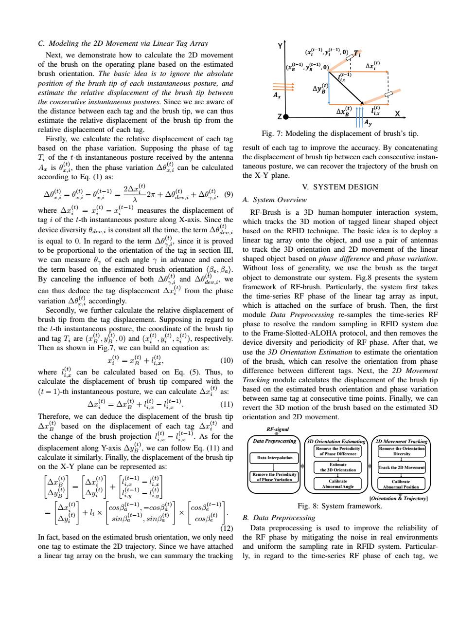
C.Modeling the 2D Movement via Linear Tag Array Next,we demonstrate how to calculate the 2D movement (x-,y-”0)T of the brush on the operating plane based on the estimated brush orientation.The basic idea is to ignore the absolute t- position of the brush tip of each instantaneous posture,and (t) estimate the relative displacement of the brush tip between the consecutive instantaneous postures.Since we are aware of the distance between each tag and the brush tip,we can thus △xB X estimate the relative displacement of the brush tip from the A relative displacement of each tag. Firstly,we calculate the relative displacement of each tag Fig.7:Modeling the displacement of brush's tip. based on the phase variation.Supposing the phase of tag result of each tag to improve the accuracy.By concatenating T;of the t-th instantaneous posture received by the antenna the displacement of brush tip between each consecutive instan- A is then the phase variation can be calculated taneous posture,we can recover the trajectory of the brush on according to Eq.(1)as: the X-Y plane. 409=09-9u-)三2△02r+a92,+Aa9 V.SYSTEM DESIGN T.i (9) A.System Overview where1)measures the displacement of RF-Brush is a 3D human-homputer interaction system, tag i of the t-th instantaneous posture along X-axis.Since the which tracks the 3D motion of tagged linear shaped object device diversityis constant all the time,the term based on the RFID technique.The basic idea is to deploy a is equal to.In regard to the term since it is proved linear tag array onto the object,and use a pair of antennas to be proportional to the orientation of the tag in section III,to track the 3D orientation and 2D movement of the linear we can measure 0 of each angle y in advance and cancel shaped object based on phase difference and phase variation. the term based on the estimated brush orientation (Be,Ba). Without loss of generality,we use the brush as the target By canceling the influence of bothandwe object to demonstrate our system.Fig.8 presents the system can thus deduce the tag displacement Ar from the phase framework of RF-brush.Particularly,the system first takes variation accordingly. the time-series RF phase of the linear tag array as input, Secondly,we further calculate the relative displacement of which is attached on the surface of brush.Then,the first brush tip from the tag displacement.Supposing in regard to module Data Preprocessing re-samples the time-series RF phase to resolve the random sampling in RFID system due the t-th instantaneous posture,the coordinate of the brush tip and tag T:are ()and ()respectively. to the Frame-Slotted-ALOHA protocol,and then removes the device diversity and periodicity of RF phase.After that,we Then as shown in Fig.7,we can build an equation as: use the 3D Orientation Estimation to estimate the orientation 9=x增+唱, (10)of the brush,which can resolve the orientation from phase where can be calculated based on Eq.(5).Thus,to difference between different tags.Next,the 2D Movement calculate the displacement of brush tip compared with the Tracking module calculates the displacement of the brush tip (-1)-th instantaneous posture,we can calculate as: based on the estimated brush orientation and phase variation △9=△8+9-) between same tag at consecutive time points.Finally,we can (11) revert the 3D motion of the brush based on the estimated 3D Therefore,we can deduce the displacement of the brush tip orientation and 2D movement. A based on the displacement of each tagx and the change of the brush projection As for the RF-signal displacement along Y-axis Au.we can follow Eq.(11)and Data Preprocessing 3D Orientation Estimating 2D Movement Tracking emove the periodicity Remove the orientation calculate it similarly.Finally,the displacement of the brush tip of Phas Diversity Data Interpolation on the X-Y plane can be represented as: Track the 2D Movemer t) △x 「(t-1)- ,(t) Calibrate Calibrate A」 △ -1)- Orientation Trajectory 4x(7 cosB(-1) (t) cosB(t-1) Fig.8:System framework. (t) t-1) △ sinBa sn6.0 cosB(t) B.Data Preprocessing (12) Data preprocessing is used to improve the reliability of In fact,based on the estimated brush orientation,we only need the RF phase by mitigating the noise in real environments one tag to estimate the 2D trajectory.Since we have attached and uniform the sampling rate in RFID system.Particular- a linear tag array on the brush,we can summary the tracking ly,in regard to the time-series RF phase of each tag,weC. Modeling the 2D Movement via Linear Tag Array Next, we demonstrate how to calculate the 2D movement of the brush on the operating plane based on the estimated brush orientation. The basic idea is to ignore the absolute position of the brush tip of each instantaneous posture, and estimate the relative displacement of the brush tip between the consecutive instantaneous postures. Since we are aware of the distance between each tag and the brush tip, we can thus estimate the relative displacement of the brush tip from the relative displacement of each tag. Firstly, we calculate the relative displacement of each tag based on the phase variation. Supposing the phase of tag Ti of the t-th instantaneous posture received by the antenna Ax is θ (t) x,i, then the phase variation ∆θ (t) x,i can be calculated according to Eq. (1) as: ∆θ (t) x,i = θ (t) x,i − θ (t−1) x,i = 2∆x (t) i λ 2π + ∆θ (t) dev,i + ∆θ (t) γ,i, (9) where ∆x (t) i = x (t) i − x (t−1) i measures the displacement of tag i of the t-th instantaneous posture along X-axis. Since the device diversity θdev,i is constant all the time, the term ∆θ (t) dev,i is equal to 0. In regard to the term ∆θ (t) γ,i, since it is proved to be proportional to the orientation of the tag in section III, we can measure θγ of each angle γ in advance and cancel the term based on the estimated brush orientation hβe, βai. By canceling the influence of both ∆θ (t) γ,i and ∆θ (t) dev,i, we can thus deduce the tag displacement ∆x (t) i from the phase variation ∆θ (t) x,i accordingly. Secondly, we further calculate the relative displacement of brush tip from the tag displacement. Supposing in regard to the t-th instantaneous posture, the coordinate of the brush tip and tag Ti are (x (t) B , y (t) B , 0) and (x (t) i , y (t) i , z (t) i ), respectively. Then as shown in Fig.7, we can build an equation as: x (t) i = x (t) B + l (t) i,x, (10) where l (t) i,x can be calculated based on Eq. (5). Thus, to calculate the displacement of brush tip compared with the (t − 1)-th instantaneous posture, we can calculate ∆x (t) i as: ∆x (t) i = ∆x (t) B + l (t) i,x − l (t−1) i,x . (11) Therefore, we can deduce the displacement of the brush tip ∆x (t) B based on the displacement of each tag ∆x (t) i and the change of the brush projection l (t) i,x − l (t−1) i,x . As for the displacement along Y-axis ∆y (t) B , we can follow Eq. (11) and calculate it similarly. Finally, the displacement of the brush tip on the X-Y plane can be represented as: " ∆x (t) B ∆y (t) B # = " ∆x (t) i ∆y (t) i # + " l (t−1) i,x − l (t) i,x l (t−1) i,y − l (t) i,y# = " ∆x (t) i ∆y (t) i # + li × " cosβ(t−1) a , −cosβ(t) a sinβ(t−1) a , sinβ(t) a # × " cosβ(t−1) e cosβ(t) e # . (12) In fact, based on the estimated brush orientation, we only need one tag to estimate the 2D trajectory. Since we have attached a linear tag array on the brush, we can summary the tracking Z 𝑻𝒊 Y ∆𝒙𝑩 (𝒕) 𝑨𝒙 𝑨𝒚 ∆𝒚𝑩 (𝒕) (𝒙𝒊 (𝒕−𝟏) , 𝒚𝒊 (𝒕−𝟏) , 𝟎) ∆𝒙𝒊 (𝒕) (𝒙𝑩 (𝒕−𝟏) , 𝒚𝑩 (𝒕−𝟏) , 𝟎) 𝒍 𝒊,𝒙 (𝒕−𝟏) 𝒍 𝒊,𝒙 (𝒕) X Fig. 7: Modeling the displacement of brush’s tip. result of each tag to improve the accuracy. By concatenating the displacement of brush tip between each consecutive instantaneous posture, we can recover the trajectory of the brush on the X-Y plane. V. SYSTEM DESIGN A. System Overview RF-Brush is a 3D human-homputer interaction system, which tracks the 3D motion of tagged linear shaped object based on the RFID technique. The basic idea is to deploy a linear tag array onto the object, and use a pair of antennas to track the 3D orientation and 2D movement of the linear shaped object based on phase difference and phase variation. Without loss of generality, we use the brush as the target object to demonstrate our system. Fig.8 presents the system framework of RF-brush. Particularly, the system first takes the time-series RF phase of the linear tag array as input, which is attached on the surface of brush. Then, the first module Data Preprocessing re-samples the time-series RF phase to resolve the random sampling in RFID system due to the Frame-Slotted-ALOHA protocol, and then removes the device diversity and periodicity of RF phase. After that, we use the 3D Orientation Estimation to estimate the orientation of the brush, which can resolve the orientation from phase difference between different tags. Next, the 2D Movement Tracking module calculates the displacement of the brush tip based on the estimated brush orientation and phase variation between same tag at consecutive time points. Finally, we can revert the 3D motion of the brush based on the estimated 3D orientation and 2D movement. Data Preprocessing Data Interpolation Remove the Periodicity of Phase Variation 3D Orientation Estimating Remove the Periodicity of Phase Difference RF-signal [Orientation & Trajectory] Estimate the 3D Orientation Calibrate Abnormal Angle 2D Movement Tracking Remove the Orientation Diversity Track the 2D Movement Calibrate Abnormal Position Fig. 8: System framework. B. Data Preprocessing Data preprocessing is used to improve the reliability of the RF phase by mitigating the noise in real environments and uniform the sampling rate in RFID system. Particularly, in regard to the time-series RF phase of each tag, we