正在加载图片...

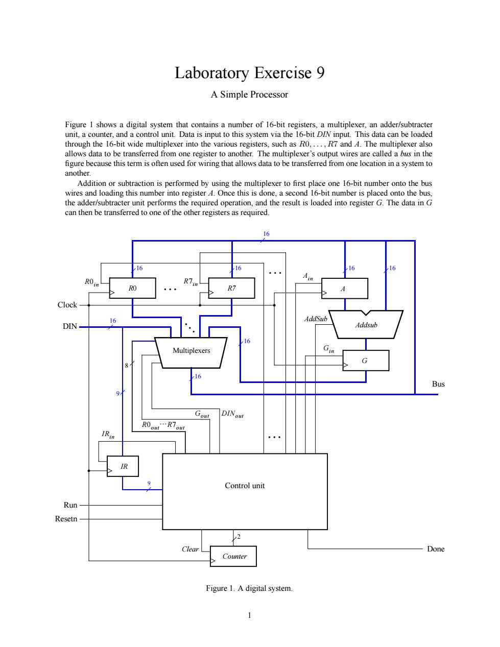
Laboratory Exercise 9 A Simple Processor through the 16-bit wide multiplexer into the various registers,such asOR7and 4.The multiplexer also allows data to be transferred from one register to another.The multiplexer's output wires are called a bus in the this term for wiring that allows data to be transferred from one location in a system to Addition or subtraction is performed by using the multiplexer to first pla e one 16-bit number onto the bus wires and loading this number into register.Once this is done.a second 16-bit number is placed onto the bus Control uni Clear Done Figure 1.A digital system Laboratory Exercise 9 A Simple Processor Figure 1 shows a digital system that contains a number of 16-bit registers, a multiplexer, an adder/subtracter unit, a counter, and a control unit. Data is input to this system via the 16-bit DIN input. This data can be loaded through the 16-bit wide multiplexer into the various registers, such as R0,...,R7 and A. The multiplexer also allows data to be transferred from one register to another. The multiplexer’s output wires are called a bus in the figure because this term is often used for wiring that allows data to be transferred from one location in a system to another. Addition or subtraction is performed by using the multiplexer to first place one 16-bit number onto the bus wires and loading this number into register A. Once this is done, a second 16-bit number is placed onto the bus, the adder/subtracter unit performs the required operation, and the result is loaded into register G. The data in G can then be transferred to one of the other registers as required. Control unit AddSub Ain Gin Run Done 9 16 16 DIN R0in Multiplexers R7in Bus Clock Gout R0out}R7out 16 R0 R7 16 8 DINout 16 IRin Addsub 16 IR 9 A G Counter 2 Clear Resetn 16 16 Figure 1. A digital system. 1