正在加载图片...

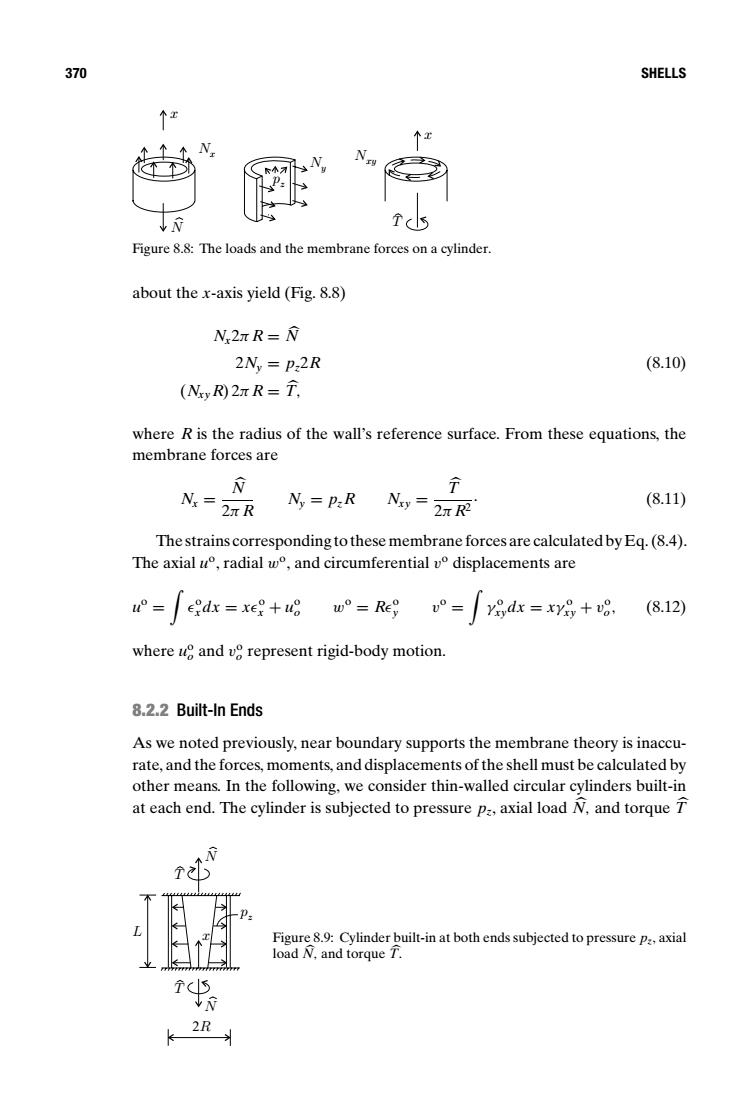
370 SHELLS 个五 Figure 8.8:The loads and the membrane forces on a cylinder. about the x-axis yield (Fig.8.8) N2nR=N 2Ny P:2R (8.10) (Nzy R)2nR=T. where R is the radius of the wall's reference surface.From these equations,the membrane forces are N Nx=2R Ny P:R Nsy =2R (8.11) The strains corresponding to these membrane forces are calculated by Eq.(8.4). The axial u°,radial w°,and circumferential v°displacements are °=ed=xe+ugw°=Regv°= yo,dx xy+vo. (8.12) where ue and ve represent rigid-body motion. 8.2.2 Built-In Ends As we noted previously,near boundary supports the membrane theory is inaccu- rate,and the forces,moments,and displacements of the shell must be calculated by other means.In the following,we consider thin-walled circular cylinders built-in at each end.The cylinder is subjected to pressure pa,axial load N.and torque Figure 8.9:Cylinder built-in at both ends subjected to pressure p:,axial load N,and torque T. k 2R370 SHELLS Nxy Nx N pz Ny x x T Figure 8.8: The loads and the membrane forces on a cylinder. about the x-axis yield (Fig. 8.8) Nx2π R = N 2Ny = pz2R (8.10) (NxyR) 2π R = T , where R is the radius of the wall’s reference surface. From these equations, the membrane forces are Nx = N 2π R Ny = pzR Nxy = T 2π R2 . (8.11) The strains corresponding to these membrane forces are calculated by Eq. (8.4). The axial uo, radial wo, and circumferential vo displacements are uo = ) o xdx = xo x + uo o wo = Ro y vo = ) γ o xydx = xγ o xy + vo o, (8.12) where uo o and vo o represent rigid-body motion. 8.2.2 Built-In Ends As we noted previously, near boundary supports the membrane theory is inaccurate, and the forces, moments, and displacements of the shell must be calculated by other means. In the following, we consider thin-walled circular cylinders built-in at each end. The cylinder is subjected to pressure pz, axial load N, and torque T pz L N N T T 2R x Figure 8.9: Cylinder built-in at both ends subjected to pressure pz, axial load N, and torque T