正在加载图片...

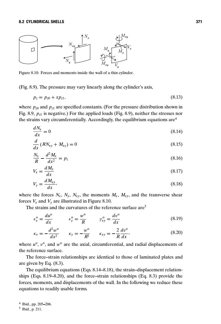
8.2 CYLINDRICAL SHELLS 371 Figure 8.10:Forces and moments inside the wall of a thin cylinder. (Fig.8.9).The pressure may vary linearly along the cylinder's axis, Pz=pao+xpa, (8.13) where Pao and Pa are specified constants.(For the pressure distribution shown in Fig.8.9,pa is negative.)For the applied loads(Fig.8.9),neither the stresses nor the strains vary circumferentially.Accordingly,the equilibrium equations are4 dN dx =0 (8.14) d (RNy+My)=0 (8.15) dx Ny dM =Pa (8.16) R dx2 v.=dM (8.17) dx dMy Vy=dx (8.18) where the forces Nr,Ny,Ny,the moments Mr,Mry,and the transverse shear forces V and V are illustrated in Figure 8.10. The strains and the curvatures of the reference surface are5 du e- wo du° (8.19) dx e= R y89= dx dPw° wo Kx= Ky= 2dv° Kxy=一 (8.20) dx2 R dx where°,v°,andw°are the axial,.circumferential,.and radial displacements of the reference surface. The force-strain relationships are identical to those of laminated plates and are given by Eq.(8.3). The equilibrium equations(Egs.8.14-8.18),the strain-displacement relation- ships (Egs.8.19-8.20),and the force-strain relationships (Eq.8.3)provide the forces,moments,and displacements of the wall.In the following we reduce these equations to readily usable forms. 4Ibid,Pp.205-206. 5 Ibid.,p.211.8.2 CYLINDRICAL SHELLS 371 Ny Nxy Nx Mxy Mxy My Mx Vy Vx Figure 8.10: Forces and moments inside the wall of a thin cylinder. (Fig. 8.9). The pressure may vary linearly along the cylinder’s axis, pz = pz0 + xpz1, (8.13) where pz0 and pz1 are specified constants. (For the pressure distribution shown in Fig. 8.9, pz1 is negative.) For the applied loads (Fig. 8.9), neither the stresses nor the strains vary circumferentially. Accordingly, the equilibrium equations are4 dNx dx = 0 (8.14) d dx (RNxy + Mxy) = 0 (8.15) Ny R − d2Mx dx2 = pz (8.16) Vx = dMx dx (8.17) Vy = dMxy dx , (8.18) where the forces Nx, Ny, Nxy, the moments Mx, Mxy, and the transverse shear forces Vx and Vy are illustrated in Figure 8.10. The strains and the curvatures of the reference surface are5 o x = duo dx o y = wo R γ o xy = dvo dx (8.19) κx = −d2wo dx2 κy = −wo R2 κxy = − 2 R dvo dx , (8.20) where uo, vo, and wo are the axial, circumferential, and radial displacements of the reference surface. The force–strain relationships are identical to those of laminated plates and are given by Eq. (8.3). The equilibrium equations (Eqs. 8.14–8.18), the strain–displacement relationships (Eqs. 8.19–8.20), and the force–strain relationships (Eq. 8.3) provide the forces, moments, and displacements of the wall. In the following we reduce these equations to readily usable forms. 4 Ibid., pp. 205–206. 5 Ibid., p. 211