正在加载图片...
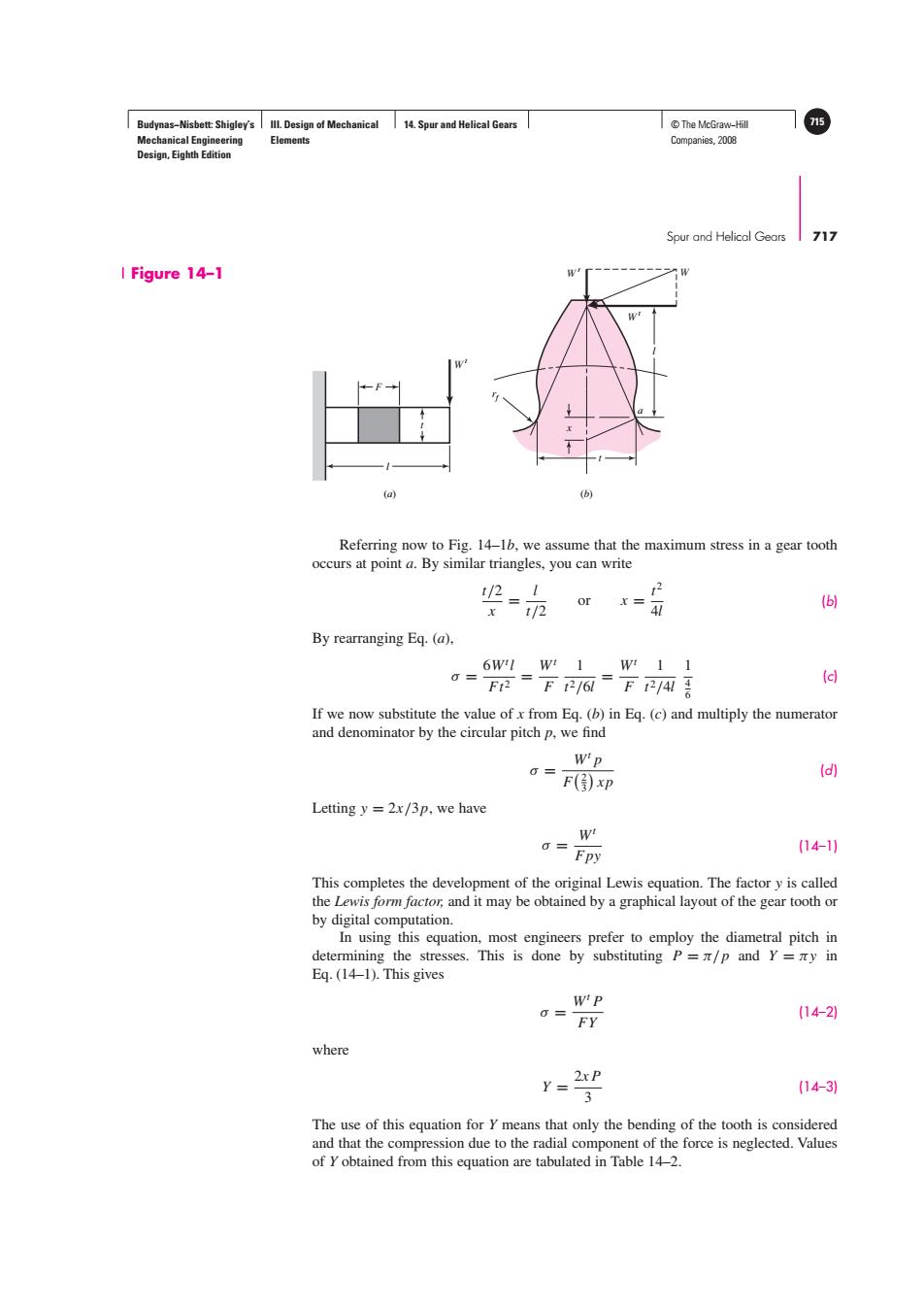
Budynas-Nisbett:Shigley's Ill.Design of Mechanical 14.Spur and Helical Gears T©The McGraw-Hil 715 Mechanical Engineering Elements Companies,2008 Design,Eighth Edition Spur and Helical Gears 717 I Figure 14-1 (a) Referring now to Fig.14-16,we assume that the maximum stress in a gear tooth occurs at point a.By similar triangles,you can write 业= x 1/2 (6) By rearranging Eq.(a), 6W1w1W11 0= F=下21a=下24吾 (d) If we now substitute the value ofx from Eq.(b)in Eq.(c)and multiply the numerator and denominator by the circular pitch p,we find Wp G=F③xP (d) Letting y =2x/3p,we have W 0= (14-11 Fpy This completes the development of the original Lewis equation.The factor y is called the Lewis form factor,and it may be obtained by a graphical layout of the gear tooth or by digital computation. In using this equation,most engineers prefer to employ the diametral pitch in determining the stresses.This is done by substituting P=z/p and Y=zy in Eq.(14-1).This gives WP 0= FY (14-2 where r=2tp (14-3) 3 The use of this equation for Y means that only the bending of the tooth is considered and that the compression due to the radial component of the force is neglected.Values of Y obtained from this equation are tabulated in Table 14-2.Budynas−Nisbett: Shigley’s Mechanical Engineering Design, Eighth Edition III. Design of Mechanical Elements 14. Spur and Helical Gears © The McGraw−Hill 715 Companies, 2008 Spur and Helical Gears 717 Figure 14–1 l F t W t W t W r l t a rf x W (a) (b) Referring now to Fig. 14–1b, we assume that the maximum stress in a gear tooth occurs at point a. By similar triangles, you can write t/2 x = l t/2 or x = t 2 4l (b) By rearranging Eq. (a), σ = 6Wt l Ft 2 = Wt F 1 t 2/6l = Wt F 1 t 2/4l 1 4 6 (c) If we now substitute the value of x from Eq. (b) in Eq. (c) and multiply the numerator and denominator by the circular pitch p, we find σ = Wt p F 2 3 xp (d) Letting y = 2x/3p, we have σ = Wt Fpy (14–1) This completes the development of the original Lewis equation. The factor y is called the Lewis form factor, and it may be obtained by a graphical layout of the gear tooth or by digital computation. In using this equation, most engineers prefer to employ the diametral pitch in determining the stresses. This is done by substituting P = π/p and Y = πy in Eq. (14–1). This gives σ = Wt P FY (14–2) where Y = 2x P 3 (14–3) The use of this equation for Y means that only the bending of the tooth is considered and that the compression due to the radial component of the force is neglected. Values of Y obtained from this equation are tabulated in Table 14–2.��