正在加载图片...
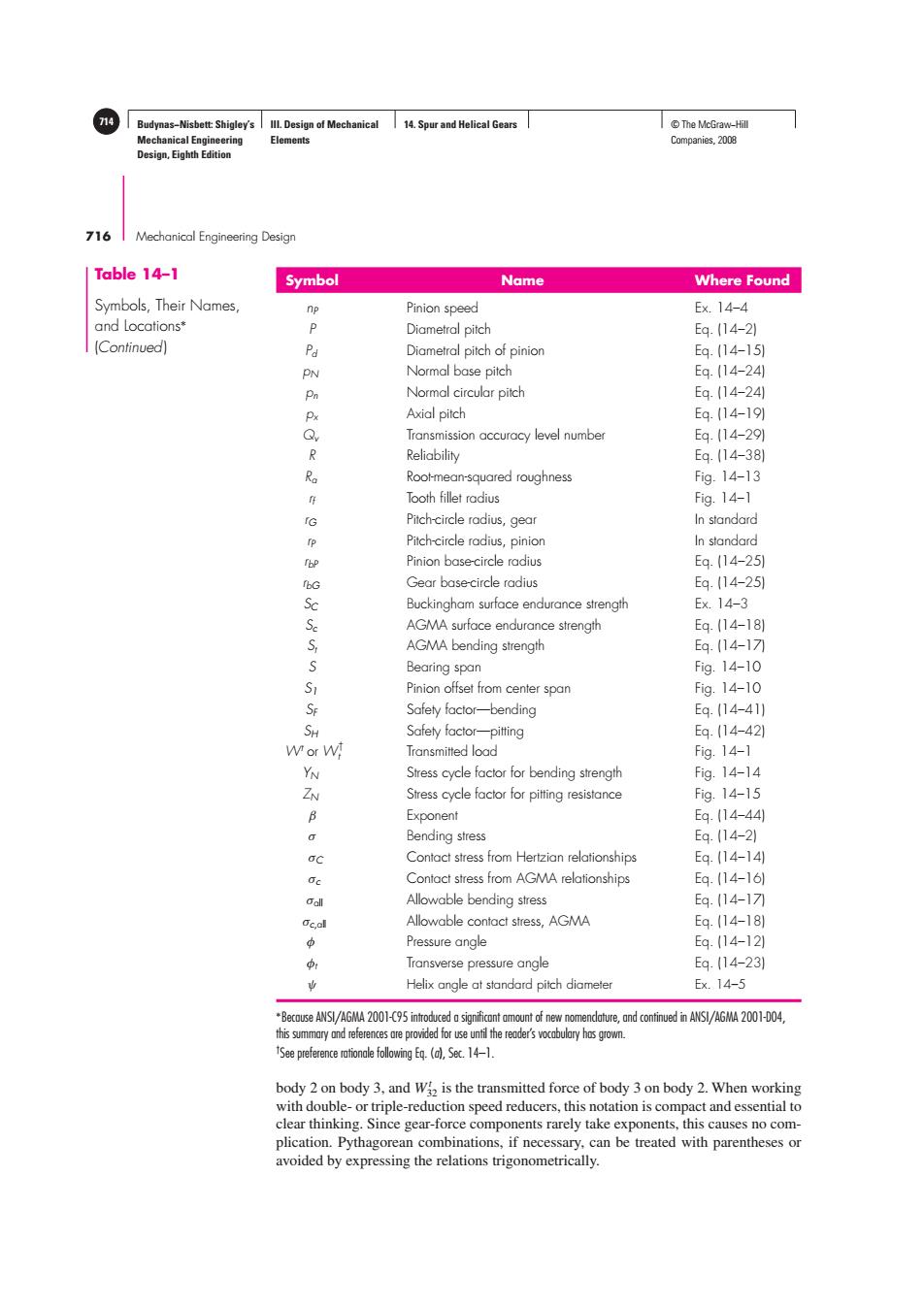
14 Budynas-Nisbett:Shigley's Ill.Design of Mechanical 14.Spur and Helical Gears ©The McGraw-Hil Mechanical Engineering Elements Companies,2008 Design,Eighth Edition 716 Mechanical Engineering Design Table 14-1 Symbol Name Where Found Symbols,Their Names, np Pinion speed Ex.14-4 and Locations' P Diametral pitch Eq.14-21 [Continued) Pd Diametral pitch of pinion Eq.(14-151 PN Normal base pitch Eq.(14-24) Pn Normal circular pitch Eq.(14-241 Px Axial pitch Eq.(14-191 Q, Transmission accuracy level number Eq.(14-291 R Reliability Eq.(14-381 R Root-mean-squared roughness Fig.14-13 Tooth fillet radius Fig.14-1 rG Pitch-circle radius,gear In standard p Pitch-circle radius,pinion In standard Tbp Pinion base-circle radius Eq.(14-251 fbG Gear base-circle radius Eq.(14-251 Sc Buckingham surface endurance strength E×.14-3 Se AGMA surface endurance strength Eq.(14-181 S AGMA bending strength Eq.14-17 Bearing span Fig.14-10 S1 Pinion offset from center span Fig.14-10 Se Safety factor-bending Eq.(14-41) SH Safely factor-pitting Eq.(14-42) Wor W! Transmitted load Fig.14-1 YN Stress cycle factor for bending strength Fig.14-14 ZN Stress cycle factor for pitting resistance Fig.14-15 B Exponent Eq.(14-44 0 Bending stress Eq.(14-2) oc Contact stress from Hertzian relationships Eq.(14-14) e Contact stress from AGMA relationships Eq.(14-161 Call Allowable bending stress Eq.14-17 Oc,all Allowable contact stress,AGMA Eq.(14-181 必 Pressure angle Eq.(14-12) Transverse pressure angle Eq.(14-23) Helix angle at standard pitch diameter Ex.14-5 Because ANSI/AGMA 2001-95inuedsignificntmo ofnew nomendatre,nd cnind in ANSI/AGMA 21-04 this summary and references are provided for use until the reader's vocabulary has grown. See preferenie following E.()Se.14-1. body 2 on body 3,and W is the transmitted force of body 3 on body 2.When working with double-or triple-reduction speed reducers,this notation is compact and essential to clear thinking.Since gear-force components rarely take exponents,this causes no com- plication.Pythagorean combinations,if necessary,can be treated with parentheses or avoided by expressing the relations trigonometrically.Budynas−Nisbett: Shigley’s Mechanical Engineering Design, Eighth Edition III. Design of Mechanical Elements 14. Spur and Helical Gears 714 © The McGraw−Hill Companies, 2008 716 Mechanical Engineering Design Symbol Name Where Found nP Pinion speed Ex. 14–4 P Diametral pitch Eq. (14–2) Pd Diametral pitch of pinion Eq. (14–15) pN Normal base pitch Eq. (14–24) pn Normal circular pitch Eq. (14–24) px Axial pitch Eq. (14–19) Qv Transmission accuracy level number Eq. (14–29) R Reliability Eq. (14–38) Ra Root-mean-squared roughness Fig. 14–13 rf Tooth fillet radius Fig. 14–1 rG Pitch-circle radius, gear In standard rP Pitch-circle radius, pinion In standard rbP Pinion base-circle radius Eq. (14–25) rbG Gear base-circle radius Eq. (14–25) SC Buckingham surface endurance strength Ex. 14–3 Sc AGMA surface endurance strength Eq. (14–18) St AGMA bending strength Eq. (14–17) S Bearing span Fig. 14–10 S1 Pinion offset from center span Fig. 14–10 SF Safety factor—bending Eq. (14–41) SH Safety factor—pitting Eq. (14–42) Wt or W† t Transmitted load Fig. 14–1 YN Stress cycle factor for bending strength Fig. 14–14 ZN Stress cycle factor for pitting resistance Fig. 14–15 β Exponent Eq. (14–44) σ Bending stress Eq. (14–2) σC Contact stress from Hertzian relationships Eq. (14–14) σc Contact stress from AGMA relationships Eq. (14–16) σall Allowable bending stress Eq. (14–17) σc,all Allowable contact stress, AGMA Eq. (14–18) φ Pressure angle Eq. (14–12) φt Transverse pressure angle Eq. (14–23) ψ Helix angle at standard pitch diameter Ex. 14–5 ∗Because ANSI/AGMA 2001-C95 introduced a significant amount of new nomenclature, and continued in ANSI/AGMA 2001-D04, this summary and references are provided for use until the reader’s vocabulary has grown. † See preference rationale following Eq. (a), Sec. 14–1. Table 14–1 Symbols, Their Names, and Locations∗ (Continued) body 2 on body 3, and Wt 32 is the transmitted force of body 3 on body 2. When working with double- or triple-reduction speed reducers, this notation is compact and essential to clear thinking. Since gear-force components rarely take exponents, this causes no complication. Pythagorean combinations, if necessary, can be treated with parentheses or avoided by expressing the relations trigonometrically