正在加载图片...
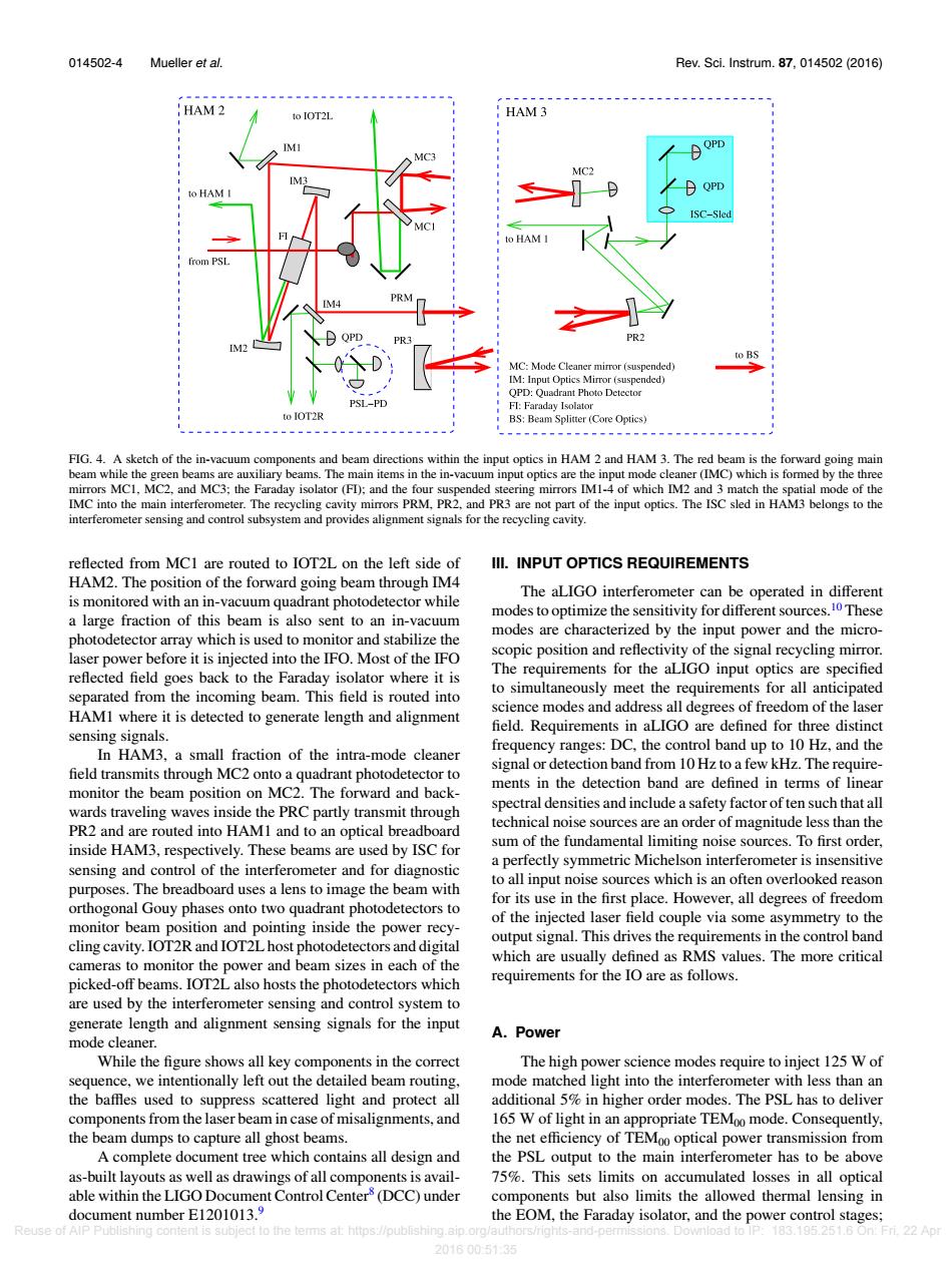
014502-4 Mueller et al. Rev.Sci.Instrum.87,014502(2016) HAM2 to IOT2L HAM 3 IMI QPD to HAM ISC-Sled o HAM rom PSL R PR2 to BS MC:Mode Cleaner mirror(suspended) IM:Input Optics Mirror (suspended) QPD:Quadrant Photo Detector PSL-PD FI:Faraday Isolator to IOT2R BS:Beam Splitter (Core Optics) FIG.4.A sketch of the in-vacuum components and beam directions within the input optics in HAM 2 and HAM 3.The red beam is the forward going main beam while the green beams are auxiliary beams.The main items in the in-vacuum input optics are the input mode cleaner(IMC)which is formed by the three mirrors MC1,MC2,and MC3;the Faraday isolator (FD);and the four suspended steering mirrors IM1-4 of which IM2 and 3 match the spatial mode of the IMC into the main interferometer.The recycling cavity mirrors PRM,PR2,and PR3 are not part of the input optics.The ISC sled in HAM3 belongs to the interferometer sensing and control subsystem and provides alignment signals for the recycling cavity. reflected from MC1 are routed to IOT2L on the left side of III.INPUT OPTICS REQUIREMENTS HAM2.The position of the forward going beam through IM4 The aLIGO interferometer can be operated in different is monitored with an in-vacuum quadrant photodetector while a large fraction of this beam is also sent to an in-vacuum modes to optimize the sensitivity for different sources.10 These photodetector array which is used to monitor and stabilize the modes are characterized by the input power and the micro- laser power before it is injected into the IFO.Most of the IFO scopic position and reflectivity of the signal recycling mirror. reflected field goes back to the Faraday isolator where it is The requirements for the aLIGO input optics are specified separated from the incoming beam.This field is routed into to simultaneously meet the requirements for all anticipated HAMI where it is detected to generate length and alignment science modes and address all degrees of freedom of the laser field.Requirements in aLIGO are defined for three distinct sensing signals. frequency ranges:DC,the control band up to 10 Hz,and the In HAM3,a small fraction of the intra-mode cleaner field transmits through MC2 onto a quadrant photodetector to signal or detection band from 10 Hz to a few kHz.The require- ments in the detection band are defined in terms of linear monitor the beam position on MC2.The forward and back- wards traveling waves inside the PRC partly transmit through spectral densities and include a safety factor of ten such that all PR2 and are routed into HAMI and to an optical breadboard technical noise sources are an order of magnitude less than the sum of the fundamental limiting noise sources.To first order. inside HAM3,respectively.These beams are used by ISC for sensing and control of the interferometer and for diagnostic a perfectly symmetric Michelson interferometer is insensitive to all input noise sources which is an often overlooked reason purposes.The breadboard uses a lens to image the beam with for its use in the first place.However,all degrees of freedom orthogonal Gouy phases onto two quadrant photodetectors to of the injected laser field couple via some asymmetry to the monitor beam position and pointing inside the power recy- output signal.This drives the requirements in the control band cling cavity.IOT2R and IOT2L host photodetectors and digital cameras to monitor the power and beam sizes in each of the which are usually defined as RMS values.The more critical picked-off beams.IOT2L also hosts the photodetectors which requirements for the IO are as follows. are used by the interferometer sensing and control system to generate length and alignment sensing signals for the input A.Power mode cleaner. While the figure shows all key components in the correct The high power science modes require to inject 125 W of sequence,we intentionally left out the detailed beam routing, mode matched light into the interferometer with less than an the baffles used to suppress scattered light and protect all additional 5%in higher order modes.The PSL has to deliver components from the laser beam in case of misalignments,and 165 W of light in an appropriate TEMoo mode.Consequently, the beam dumps to capture all ghost beams. the net efficiency of TEMoo optical power transmission from A complete document tree which contains all design and the PSL output to the main interferometer has to be above as-built layouts as well as drawings of all components is avail- 75%.This sets limits on accumulated losses in all optical able within the LIGO Document Control Center(DCC)under components but also limits the allowed thermal lensing in document number E1201013.9 the EOM,the Faraday isolator,and the power control stages; Reuse of AlP Publishing content is subject to the terms at:https://publishing.aip.org/authors/rights nd-pem sions.Download to 183195.251.60nFi22A1 20160051:35014502-4 Mueller et al. Rev. Sci. Instrum. 87, 014502 (2016) FIG. 4. A sketch of the in-vacuum components and beam directions within the input optics in HAM 2 and HAM 3. The red beam is the forward going main beam while the green beams are auxiliary beams. The main items in the in-vacuum input optics are the input mode cleaner (IMC) which is formed by the three mirrors MC1, MC2, and MC3; the Faraday isolator (FI); and the four suspended steering mirrors IM1-4 of which IM2 and 3 match the spatial mode of the IMC into the main interferometer. The recycling cavity mirrors PRM, PR2, and PR3 are not part of the input optics. The ISC sled in HAM3 belongs to the interferometer sensing and control subsystem and provides alignment signals for the recycling cavity. reflected from MC1 are routed to IOT2L on the left side of HAM2. The position of the forward going beam through IM4 is monitored with an in-vacuum quadrant photodetector while a large fraction of this beam is also sent to an in-vacuum photodetector array which is used to monitor and stabilize the laser power before it is injected into the IFO. Most of the IFO reflected field goes back to the Faraday isolator where it is separated from the incoming beam. This field is routed into HAM1 where it is detected to generate length and alignment sensing signals. In HAM3, a small fraction of the intra-mode cleaner field transmits through MC2 onto a quadrant photodetector to monitor the beam position on MC2. The forward and backwards traveling waves inside the PRC partly transmit through PR2 and are routed into HAM1 and to an optical breadboard inside HAM3, respectively. These beams are used by ISC for sensing and control of the interferometer and for diagnostic purposes. The breadboard uses a lens to image the beam with orthogonal Gouy phases onto two quadrant photodetectors to monitor beam position and pointing inside the power recycling cavity. IOT2R and IOT2L host photodetectors and digital cameras to monitor the power and beam sizes in each of the picked-off beams. IOT2L also hosts the photodetectors which are used by the interferometer sensing and control system to generate length and alignment sensing signals for the input mode cleaner. While the figure shows all key components in the correct sequence, we intentionally left out the detailed beam routing, the baffles used to suppress scattered light and protect all components from the laser beam in case of misalignments, and the beam dumps to capture all ghost beams. A complete document tree which contains all design and as-built layouts as well as drawings of all components is available within the LIGO Document Control Center8 (DCC) under document number E1201013.9 III. INPUT OPTICS REQUIREMENTS The aLIGO interferometer can be operated in different modes to optimize the sensitivity for different sources.10 These modes are characterized by the input power and the microscopic position and reflectivity of the signal recycling mirror. The requirements for the aLIGO input optics are specified to simultaneously meet the requirements for all anticipated science modes and address all degrees of freedom of the laser field. Requirements in aLIGO are defined for three distinct frequency ranges: DC, the control band up to 10 Hz, and the signal or detection band from 10 Hz to a few kHz. The requirements in the detection band are defined in terms of linear spectral densities and include a safety factor of ten such that all technical noise sources are an order of magnitude less than the sum of the fundamental limiting noise sources. To first order, a perfectly symmetric Michelson interferometer is insensitive to all input noise sources which is an often overlooked reason for its use in the first place. However, all degrees of freedom of the injected laser field couple via some asymmetry to the output signal. This drives the requirements in the control band which are usually defined as RMS values. The more critical requirements for the IO are as follows. A. Power The high power science modes require to inject 125 W of mode matched light into the interferometer with less than an additional 5% in higher order modes. The PSL has to deliver 165 W of light in an appropriate TEM00 mode. Consequently, the net efficiency of TEM00 optical power transmission from the PSL output to the main interferometer has to be above 75%. This sets limits on accumulated losses in all optical components but also limits the allowed thermal lensing in the EOM, the Faraday isolator, and the power control stages; Reuse of AIP Publishing content is subject to the terms at: https://publishing.aip.org/authors/rights-and-permissions. Download to IP: 183.195.251.6 On: Fri, 22 Apr 2016 00:51:35