正在加载图片...
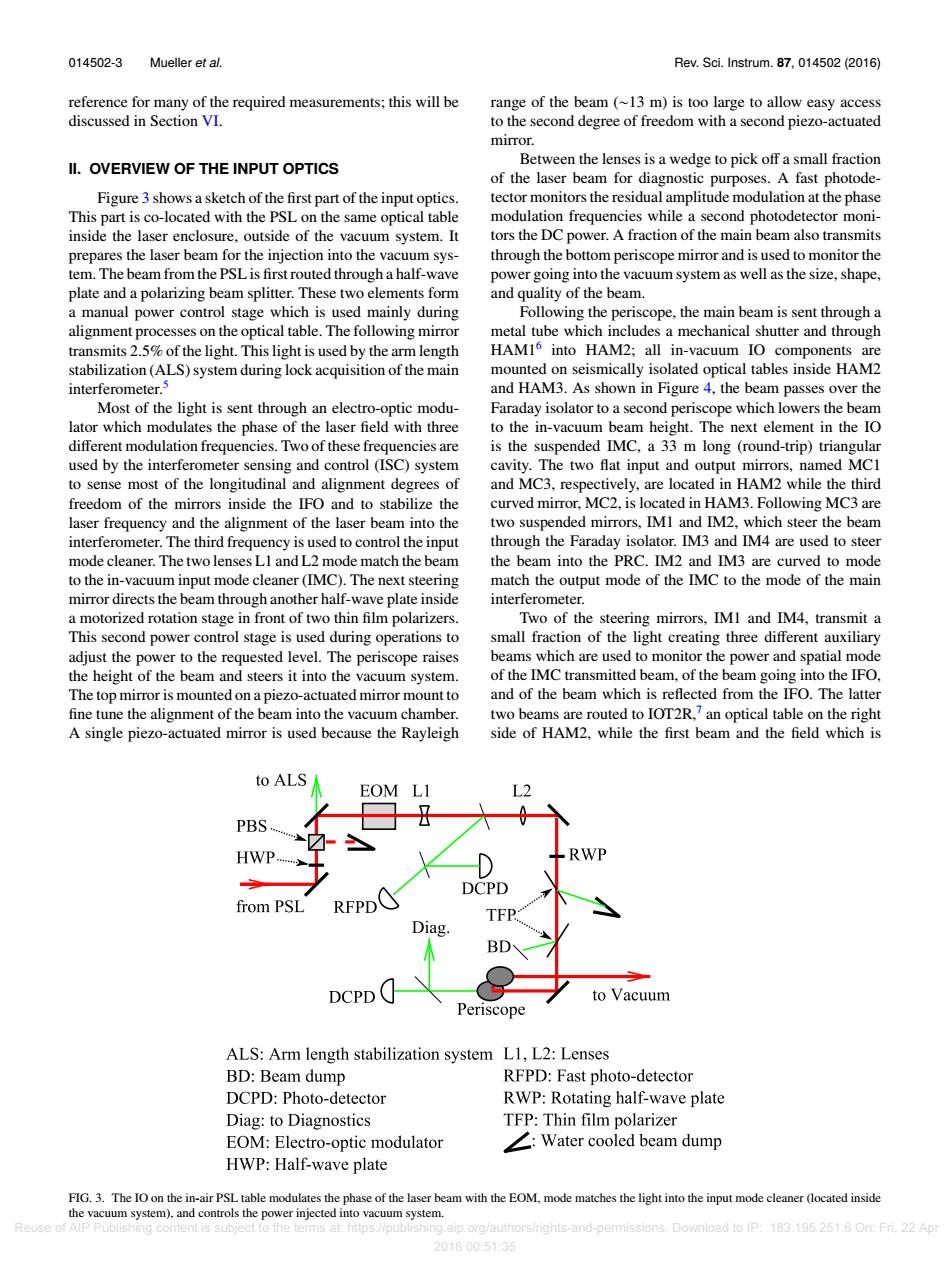
014502-3 Mueller et al. Rev.Sci.Instrum.87,014502(2016) reference for many of the required measurements;this will be range of the beam (~13 m)is too large to allow easy access discussed in Section VI. to the second degree of freedom with a second piezo-actuated mirror. Between the lenses is a wedge to pick off a small fraction II.OVERVIEW OF THE INPUT OPTICS of the laser beam for diagnostic purposes.A fast photode- Figure 3 shows a sketch of the first part of the input optics. tector monitors the residual amplitude modulation at the phase This part is co-located with the PSL on the same optical table modulation frequencies while a second photodetector moni- inside the laser enclosure,outside of the vacuum system.It tors the DC power.A fraction of the main beam also transmits prepares the laser beam for the injection into the vacuum sys- through the bottom periscope mirror and is used to monitor the tem.The beam from the PSL is first routed through a half-wave power going into the vacuum system as well as the size,shape, plate and a polarizing beam splitter.These two elements form and quality of the beam. a manual power control stage which is used mainly during Following the periscope,the main beam is sent through a alignment processes on the optical table.The following mirror metal tube which includes a mechanical shutter and through transmits 2.5%of the light.This light is used by the arm length HAM16 into HAM2;all in-vacuum IO components are stabilization (ALS)system during lock acquisition of the main mounted on seismically isolated optical tables inside HAM2 interferometer.3 and HAM3.As shown in Figure 4,the beam passes over the Most of the light is sent through an electro-optic modu- Faraday isolator to a second periscope which lowers the beam lator which modulates the phase of the laser field with three to the in-vacuum beam height.The next element in the IO different modulation frequencies.Two of these frequencies are is the suspended IMC,a 33 m long (round-trip)triangular used by the interferometer sensing and control (ISC)system cavity.The two flat input and output mirrors,named MCI to sense most of the longitudinal and alignment degrees of and MC3,respectively,are located in HAM2 while the third freedom of the mirrors inside the IFO and to stabilize the curved mirror,MC2,is located in HAM3.Following MC3 are laser frequency and the alignment of the laser beam into the two suspended mirrors,IMI and IM2.which steer the beam interferometer.The third frequency is used to control the input through the Faraday isolator.IM3 and IM4 are used to steer mode cleaner.The two lenses LI and L2 mode match the beam the beam into the PRC.IM2 and IM3 are curved to mode to the in-vacuum input mode cleaner (IMC).The next steering match the output mode of the IMC to the mode of the main mirror directs the beam through another half-wave plate inside interferometer. a motorized rotation stage in front of two thin film polarizers. Two of the steering mirrors,IMI and IM4,transmit a This second power control stage is used during operations to small fraction of the light creating three different auxiliary adjust the power to the requested level.The periscope raises beams which are used to monitor the power and spatial mode the height of the beam and steers it into the vacuum system. of the IMC transmitted beam,of the beam going into the IFO, The top mirror is mounted on a piezo-actuated mirror mount to and of the beam which is reflected from the IFO.The latter fine tune the alignment of the beam into the vacuum chamber. two beams are routed to IOT2R,7 an optical table on the right A single piezo-actuated mirror is used because the Rayleigh side of HAM2,while the first beam and the field which is to ALS EOM PBS HWP RWP DCPD from PSL REPD Diag. BD DCPD to Vacuum Periscope ALS:Arm length stabilization system L1,L2:Lenses BD:Beam dump RFPD:Fast photo-detector DCPD:Photo-detector RWP:Rotating half-wave plate Diag:to Diagnostics TFP:Thin film polarizer EOM:Electro-optic modulator ∠:Water cooled beam dump HWP:Half-wave plate FIG.3.The IO on the in-air PSL table modulates the phase of the laser beam with the EOM,mode matches the light into the input mode cleaner (located inside the vacuum system),and controls the power injected into vacuum system. Reuse of AlP Publishing content is subject to the terms at:https://publishing.aip.org/authors/rights-and-permissions.Download to IP:183.195.251.6 On:Fri.22 Apr 20160051:35014502-3 Mueller et al. Rev. Sci. Instrum. 87, 014502 (2016) reference for many of the required measurements; this will be discussed in Section VI. II. OVERVIEW OF THE INPUT OPTICS Figure 3 shows a sketch of the first part of the input optics. This part is co-located with the PSL on the same optical table inside the laser enclosure, outside of the vacuum system. It prepares the laser beam for the injection into the vacuum system. The beam from the PSL is first routed through a half-wave plate and a polarizing beam splitter. These two elements form a manual power control stage which is used mainly during alignment processes on the optical table. The following mirror transmits 2.5% of the light. This light is used by the arm length stabilization (ALS) system during lock acquisition of the main interferometer.5 Most of the light is sent through an electro-optic modulator which modulates the phase of the laser field with three different modulation frequencies. Two of these frequencies are used by the interferometer sensing and control (ISC) system to sense most of the longitudinal and alignment degrees of freedom of the mirrors inside the IFO and to stabilize the laser frequency and the alignment of the laser beam into the interferometer. The third frequency is used to control the input mode cleaner. The two lenses L1 and L2 mode match the beam to the in-vacuum input mode cleaner (IMC). The next steering mirror directs the beam through another half-wave plate inside a motorized rotation stage in front of two thin film polarizers. This second power control stage is used during operations to adjust the power to the requested level. The periscope raises the height of the beam and steers it into the vacuum system. The top mirror is mounted on a piezo-actuated mirror mount to fine tune the alignment of the beam into the vacuum chamber. A single piezo-actuated mirror is used because the Rayleigh range of the beam (∼13 m) is too large to allow easy access to the second degree of freedom with a second piezo-actuated mirror. Between the lenses is a wedge to pick off a small fraction of the laser beam for diagnostic purposes. A fast photodetector monitors the residual amplitude modulation at the phase modulation frequencies while a second photodetector monitors the DC power. A fraction of the main beam also transmits through the bottom periscope mirror and is used to monitor the power going into the vacuum system as well as the size, shape, and quality of the beam. Following the periscope, the main beam is sent through a metal tube which includes a mechanical shutter and through HAM16 into HAM2; all in-vacuum IO components are mounted on seismically isolated optical tables inside HAM2 and HAM3. As shown in Figure 4, the beam passes over the Faraday isolator to a second periscope which lowers the beam to the in-vacuum beam height. The next element in the IO is the suspended IMC, a 33 m long (round-trip) triangular cavity. The two flat input and output mirrors, named MC1 and MC3, respectively, are located in HAM2 while the third curved mirror, MC2, is located in HAM3. Following MC3 are two suspended mirrors, IM1 and IM2, which steer the beam through the Faraday isolator. IM3 and IM4 are used to steer the beam into the PRC. IM2 and IM3 are curved to mode match the output mode of the IMC to the mode of the main interferometer. Two of the steering mirrors, IM1 and IM4, transmit a small fraction of the light creating three different auxiliary beams which are used to monitor the power and spatial mode of the IMC transmitted beam, of the beam going into the IFO, and of the beam which is reflected from the IFO. The latter two beams are routed to IOT2R,7 an optical table on the right side of HAM2, while the first beam and the field which is FIG. 3. The IO on the in-air PSL table modulates the phase of the laser beam with the EOM, mode matches the light into the input mode cleaner (located inside the vacuum system), and controls the power injected into vacuum system. Reuse of AIP Publishing content is subject to the terms at: https://publishing.aip.org/authors/rights-and-permissions. Download to IP: 183.195.251.6 On: Fri, 22 Apr 2016 00:51:35