正在加载图片...
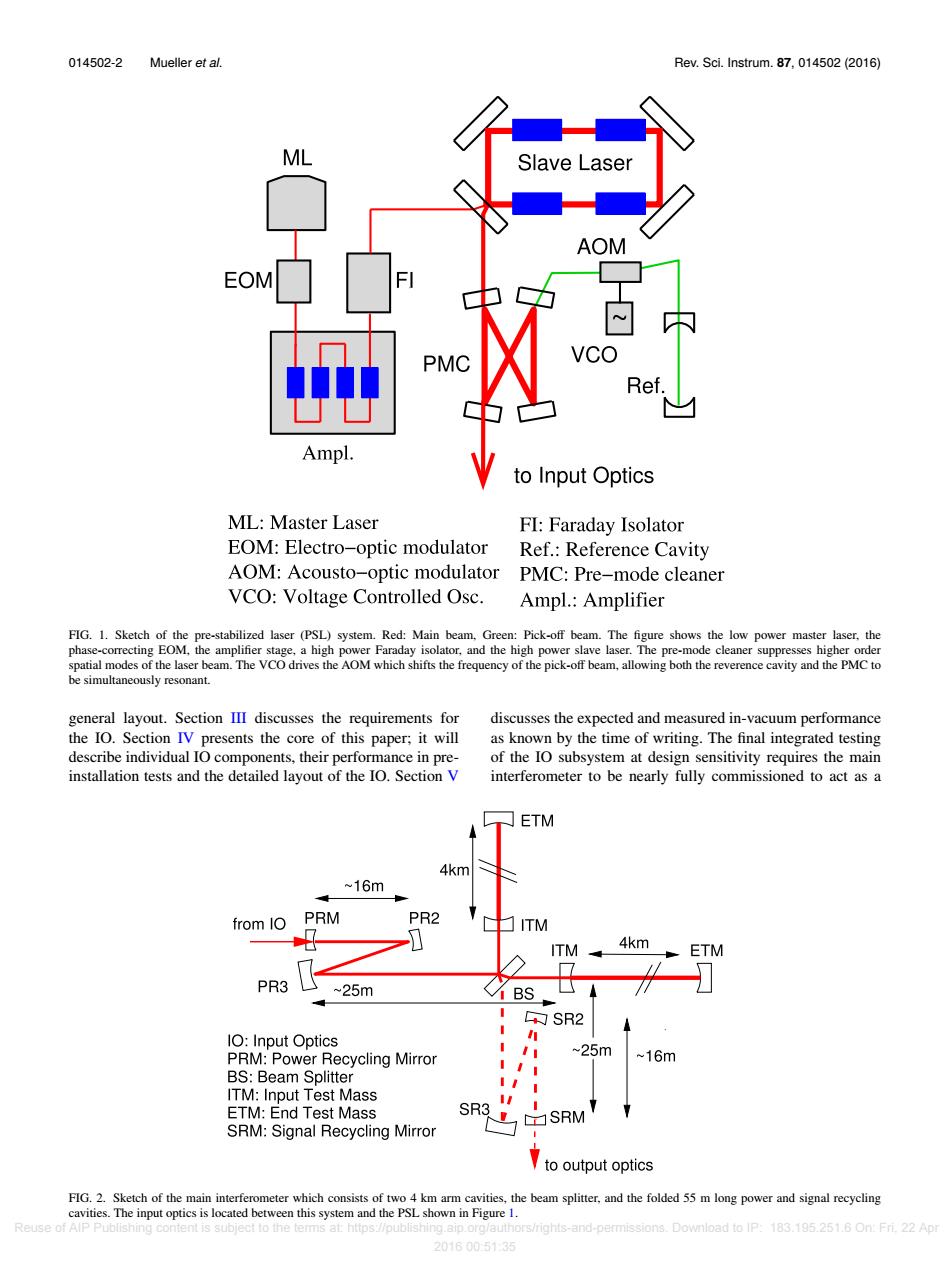
014502-2 Mueller et al. Rev.Sci.Instrum.87,014502(2016) Slave Laser AO EO VCO Ref Ampl. to Input Optics ML:Master Laser FI:Faraday Isolator EOM:Electro-optic modulator Ref.:Reference Cavity AOM:Acousto-optic modulator PMC:Pre-mode cleaner VCO:Voltage Controlled Osc. Ampl.:Amplifier FIG.1.Sketch of the pre-stabilized laser (PSL)system.Red:Main beam,Green:Pick-off beam.The figure shows the low power master laser,the phase-correcting EOM,the amplifier stage,a high power Faraday isolator,and the high power slave laser.The pre-mode cleaner suppresses higher order spatial modes of the laser beam.The VCO drives the AOM which shifts the frequency of the pick-off beam,allowing both the reverence cavity and the PMC to be simultaneously resonant. general layout.Section III discusses the requirements for discusses the expected and measured in-vacuum performance the IO.Section IV presents the core of this paper;it will as known by the time of writing.The final integrated testing describe individual IO components,their performance in pre- of the IO subsystem at design sensitivity requires the main installation tests and the detailed layout of the IO.Section V interferometer to be nearly fully commissioned to act as a ETM 4km ~16m from IO PRM PR2 ITM ITM 4km ETM 7 PR3 ~25m √MBS SR2 1O:Input Optics h PRM:Power Recycling Mirror ~25m ~16m BS:Beam Splitter ITM:Input Test Mass I ETM:End Test Mass SR3 SRM SRM:Signal Recycling Mirror to output optics FIG.2.Sketch of the main interferometer which consists of two 4 km arm cavities,the beam splitter,and the folded 55 m long power and signal recycling cavities.The input optics is located between this system and the PSL shown in Figure 1. Reuse of AlP Publishing content is subject to the terms at:https://publishing.aip.org/authors/rights-and-permissions.Download to IP:183.195.251.6 On:Fri.22 Apr 20160051:35014502-2 Mueller et al. Rev. Sci. Instrum. 87, 014502 (2016) FIG. 1. Sketch of the pre-stabilized laser (PSL) system. Red: Main beam, Green: Pick-off beam. The figure shows the low power master laser, the phase-correcting EOM, the amplifier stage, a high power Faraday isolator, and the high power slave laser. The pre-mode cleaner suppresses higher order spatial modes of the laser beam. The VCO drives the AOM which shifts the frequency of the pick-off beam, allowing both the reverence cavity and the PMC to be simultaneously resonant. general layout. Section III discusses the requirements for the IO. Section IV presents the core of this paper; it will describe individual IO components, their performance in preinstallation tests and the detailed layout of the IO. Section V discusses the expected and measured in-vacuum performance as known by the time of writing. The final integrated testing of the IO subsystem at design sensitivity requires the main interferometer to be nearly fully commissioned to act as a FIG. 2. Sketch of the main interferometer which consists of two 4 km arm cavities, the beam splitter, and the folded 55 m long power and signal recycling cavities. The input optics is located between this system and the PSL shown in Figure 1. Reuse of AIP Publishing content is subject to the terms at: https://publishing.aip.org/authors/rights-and-permissions. Download to IP: 183.195.251.6 On: Fri, 22 Apr 2016 00:51:35