正在加载图片...

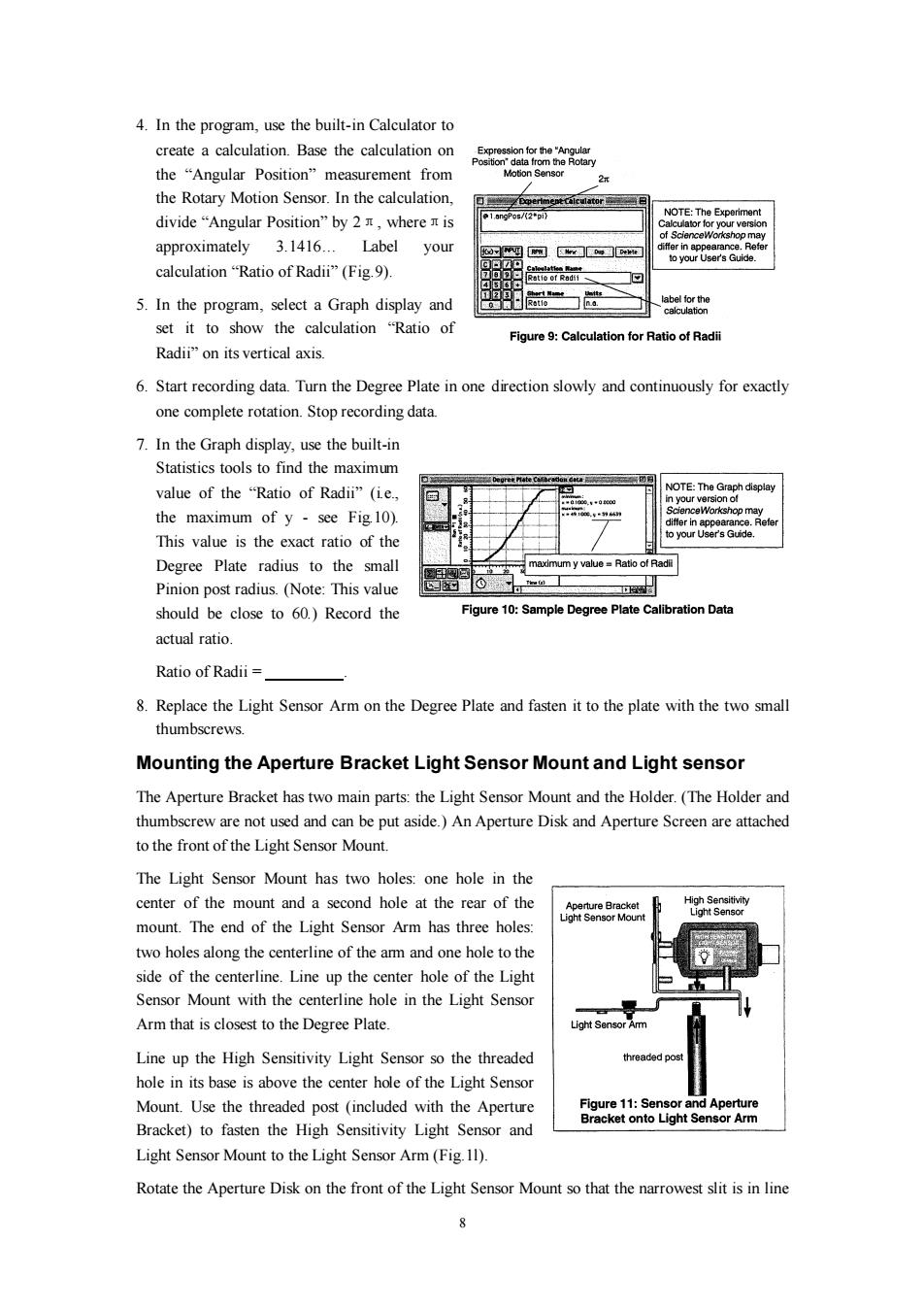
4.In the program,use the built-in Calculator to create a calculation.Base the calculation on the“Angular Position”measurement from Votion Senso the Rotary Motion Sensor.In the calculation, 1.angPos/(2pi) NOTE:The Experiment divide“Angular Position'”by2T,where is Calculator for your version of ScienceWorkshop may approximately 3.1416...Label your differ in appearance.Refer to your User's Guide. calculation“Ratio of Radii”(Fig.9). tatio of Radii 5.In the program,select a Graph display and label for the calculation set it to show the calculation "Ratio of Figure 9:Calculation for Ratio of Radii Radii"on its vertical axis. 6.Start recording data.Turn the Degree Plate in one direction slowly and continuously for exactly one complete rotation.Stop recording data. 7.In the Graph display,use the built-in Statistics tools to find the maximum value of the "Ratio of Radii"(ie., NOTE:The Graph dispiay ersion of the maximum of y-see Fig.10). iffer in appearance.Refe This value is the exact ratio of the your User's Guide. Degree Plate radius to the small maximum y value=Ratio of Radi Pinion post radius.(Note:This value 工 should be close to 60.)Record the Figure 10:Sample Degree Plate Calibration Data actual ratio Ratio of Radii 8.Replace the Light Sensor Arm on the Degree Plate and fasten it to the plate with the two small thumbscrews. Mounting the Aperture Bracket Light Sensor Mount and Light sensor The Aperture Bracket has two main parts:the Light Sensor Mount and the Holder.(The Holder and thumbscrew are not used and can be put aside.)An Aperture Disk and Aperture Screen are attached to the front of the Light Sensor Mount. The Light Sensor Mount has two holes:one hole in the center of the mount and a second hole at the rear of the Aperture Bracket High Sensitivity Light Sensor Mount Light Sensor mount.The end of the Light Sensor Arm has three holes: two holes along the centerline of the am and one hole to the side of the centerline.Line up the center hole of the Light Sensor Mount with the centerline hole in the Light Sensor Arm that is closest to the Degree Plate. Light Sensor Arm Line up the High Sensitivity Light Sensor so the threaded threaded post hole in its base is above the center hole of the Light Sensor Mount.Use the threaded post (included with the Aperture Figure 11:Sensor and Aperture Bracket onto Light Sensor Arm Bracket)to fasten the High Sensitivity Light Sensor and Light Sensor Mount to the Light Sensor Arm(Fig.11). Rotate the Aperture Disk on the front of the Light Sensor Mount so that the narrowest slit is in line8 4. In the program, use the built-in Calculator to create a calculation. Base the calculation on the “Angular Position” measurement from the Rotary Motion Sensor. In the calculation, divide “Angular Position” by 2π, whereπis approximately 3.1416… Label your calculation “Ratio of Radii” (Fig.9). 5. In the program, select a Graph display and set it to show the calculation “Ratio of Radii” on its vertical axis. 6. Start recording data. Turn the Degree Plate in one direction slowly and continuously for exactly one complete rotation. Stop recording data. 7. In the Graph display, use the built-in Statistics tools to find the maximum value of the “Ratio of Radii” (i.e., the maximum of y - see Fig.10). This value is the exact ratio of the Degree Plate radius to the small Pinion post radius. (Note: This value should be close to 60.) Record the actual ratio. Ratio of Radii = . 8. Replace the Light Sensor Arm on the Degree Plate and fasten it to the plate with the two small thumbscrews. Mounting the Aperture Bracket Light Sensor Mount and Light sensor The Aperture Bracket has two main parts: the Light Sensor Mount and the Holder. (The Holder and thumbscrew are not used and can be put aside.) An Aperture Disk and Aperture Screen are attached to the front of the Light Sensor Mount. The Light Sensor Mount has two holes: one hole in the center of the mount and a second hole at the rear of the mount. The end of the Light Sensor Arm has three holes: two holes along the centerline of the arm and one hole to the side of the centerline. Line up the center hole of the Light Sensor Mount with the centerline hole in the Light Sensor Arm that is closest to the Degree Plate. Line up the High Sensitivity Light Sensor so the threaded hole in its base is above the center hole of the Light Sensor Mount. Use the threaded post (included with the Aperture Bracket) to fasten the High Sensitivity Light Sensor and Light Sensor Mount to the Light Sensor Arm (Fig.1l). Rotate the Aperture Disk on the front of the Light Sensor Mount so that the narrowest slit is in line