正在加载图片...

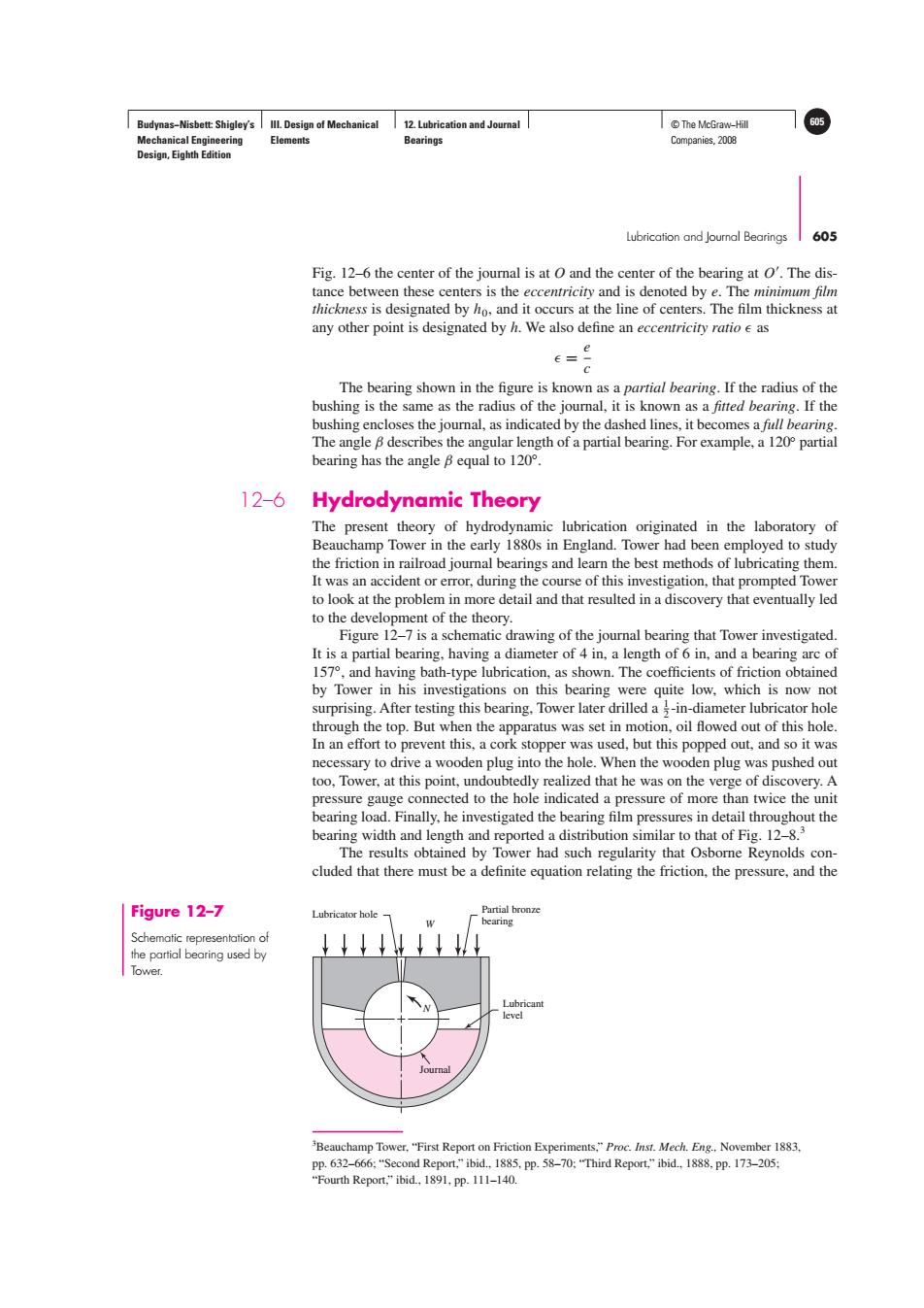
Budynas-Nisbett:Shigley's Ill.Design of Mechanical 12.Lubrication and Journal T©The McGraw-Hill 605 Mechanical Engineering Elements Bearings Companies,2008 Design,Eighth Edition Lubrication and Joumnal Bearings 605 Fig.12-6 the center of the journal is at O and the center of the bearing at O'.The dis- tance between these centers is the eccentricity and is denoted by e.The minimum film thickness is designated by ho,and it occurs at the line of centers.The film thickness at any other point is designated by h.We also define an eccentricity ratio e as e The bearing shown in the figure is known as a partial bearing.If the radius of the bushing is the same as the radius of the journal,it is known as a fitted bearing.If the bushing encloses the journal,as indicated by the dashed lines,it becomes a full bearing. The angle 8 describes the angular length of a partial bearing.For example,a 120 partial bearing has the angle B equal to 120. 12-6 Hydrodynamic Theory The present theory of hydrodynamic lubrication originated in the laboratory of Beauchamp Tower in the early 1880s in England.Tower had been employed to study the friction in railroad journal bearings and learn the best methods of lubricating them. It was an accident or error,during the course of this investigation,that prompted Tower to look at the problem in more detail and that resulted in a discovery that eventually led to the development of the theory. Figure 12-7 is a schematic drawing of the journal bearing that Tower investigated. It is a partial bearing,having a diameter of 4 in,a length of 6 in,and a bearing arc of 157,and having bath-type lubrication,as shown.The coefficients of friction obtained by Tower in his investigations on this bearing were quite low,which is now not surprising.After testing this bearing.Tower later drilled a -in-diameter lubricator hole through the top.But when the apparatus was set in motion,oil flowed out of this hole. In an effort to prevent this,a cork stopper was used,but this popped out,and so it was necessary to drive a wooden plug into the hole.When the wooden plug was pushed out too,Tower,at this point,undoubtedly realized that he was on the verge of discovery.A pressure gauge connected to the hole indicated a pressure of more than twice the unit bearing load.Finally,he investigated the bearing film pressures in detail throughout the bearing width and length and reported a distribution similar to that of Fig.12-8.3 The results obtained by Tower had such regularity that Osborne Reynolds con- cluded that there must be a definite equation relating the friction,the pressure,and the Figure 12-7 Lubricator hole- Partial bronze bearing Schematic representation of the partial bearing used by ↓↓↓ Tower. Lubricant level Beauchamp Tower,"First Report on Friction Experiments,"Proc.Inst.Mech.Eng.,November 1883. pp.632-666:"Second Report."ibid.,1885,pp.58-70:"Third Report,"ibid.,1888.pp.173-205; "Fourth Report,"ibid.,1891,pp.111-140.Budynas−Nisbett: Shigley’s Mechanical Engineering Design, Eighth Edition III. Design of Mechanical Elements 12. Lubrication and Journal Bearings © The McGraw−Hill 605 Companies, 2008 Lubrication and Journal Bearings 605 3 Beauchamp Tower, “First Report on Friction Experiments,” Proc. Inst. Mech. Eng., November 1883, pp. 632–666; “Second Report,” ibid., 1885, pp. 58–70; “Third Report,” ibid., 1888, pp. 173–205; “Fourth Report,” ibid., 1891, pp. 111–140. Fig. 12–6 the center of the journal is at O and the center of the bearing at O . The distance between these centers is the eccentricity and is denoted by e. The minimum film thickness is designated by h0, and it occurs at the line of centers. The film thickness at any other point is designated by h. We also define an eccentricity ratio as = e c The bearing shown in the figure is known as a partial bearing. If the radius of the bushing is the same as the radius of the journal, it is known as a fitted bearing. If the bushing encloses the journal, as indicated by the dashed lines, it becomes a full bearing. The angle β describes the angular length of a partial bearing. For example, a 120◦ partial bearing has the angle β equal to 120◦. 12–6 Hydrodynamic Theory The present theory of hydrodynamic lubrication originated in the laboratory of Beauchamp Tower in the early 1880s in England. Tower had been employed to study the friction in railroad journal bearings and learn the best methods of lubricating them. It was an accident or error, during the course of this investigation, that prompted Tower to look at the problem in more detail and that resulted in a discovery that eventually led to the development of the theory. Figure 12–7 is a schematic drawing of the journal bearing that Tower investigated. It is a partial bearing, having a diameter of 4 in, a length of 6 in, and a bearing arc of 157◦, and having bath-type lubrication, as shown. The coefficients of friction obtained by Tower in his investigations on this bearing were quite low, which is now not surprising. After testing this bearing, Tower later drilled a 1 2 -in-diameter lubricator hole through the top. But when the apparatus was set in motion, oil flowed out of this hole. In an effort to prevent this, a cork stopper was used, but this popped out, and so it was necessary to drive a wooden plug into the hole. When the wooden plug was pushed out too, Tower, at this point, undoubtedly realized that he was on the verge of discovery. A pressure gauge connected to the hole indicated a pressure of more than twice the unit bearing load. Finally, he investigated the bearing film pressures in detail throughout the bearing width and length and reported a distribution similar to that of Fig. 12–8.3 The results obtained by Tower had such regularity that Osborne Reynolds concluded that there must be a definite equation relating the friction, the pressure, and the Figure 12–7 Schematic representation of the partial bearing used by Tower. N Journal Lubricant level Lubricator hole Partial bronze W bearing�