正在加载图片...
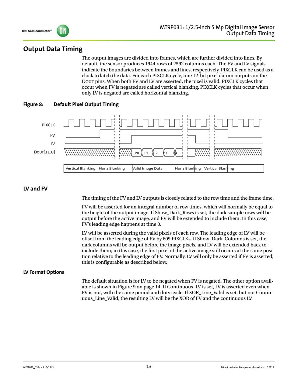
ON MTP31:1/25-inch5 Output Data Timing doe ouo prous 1592 duces 1944 rows of 2592 columns each.Ih lockch thedat.Forach XCLKYee pixel dat d as a um ou puts on the DoUr pins.When both FV and LV are asserted,the pixel is valid.PIXCLK cycles that Figure 8:Default Pixel Output Timing PIXCLK 几几几几Π几几几几Π几几 V Dour[11:0] M呱23::Yh☑ Vertical Blanking oriz Blanking Valid Image Data Horiz Blanking Vertical Blaning LVand FV The timing of the FVand LVoutputs is closely related to the row time and the frame time cappme efore the active image,and FV will be extended to include them.In this case, LV will be asse ed during the valid pixels of eacl y The leadi offset from the leading of F by 609 PIXCLKs.If Show Dark Columns is set.the dark columns will be output before the image pixels,and LV will be extended back to nclude them;in this case,the first pixel of th low LV Format Options The default situation is for LV to be negated when FV is negated.The other option avail- Contin.MT9P031_DS Rev. J 5/15 EN 13 ©Semiconductor Components Industries, LLC,2015. MT9P031: 1/2.5-Inch 5 Mp Digital Image Sensor Output Data Timing Output Data Timing The output images are divided into frames, which are further divided into lines. By default, the sensor produces 1944 rows of 2592 columns each. The FV and LV signals indicate the boundaries between frames and lines, respectively. PIXCLK can be used as a clock to latch the data. For each PIXCLK cycle, one 12-bit pixel datum outputs on the DOUT pins. When both FV and LV are asserted, the pixel is valid. PIXCLK cycles that occur when FV is negated are called vertical blanking. PIXCLK cycles that occur when only LV is negated are called horizontal blanking. Figure 8: Default Pixel Output Timing LV and FV The timing of the FV and LV outputs is closely related to the row time and the frame time. FV will be asserted for an integral number of row times, which will normally be equal to the height of the output image. If Show_Dark_Rows is set, the dark sample rows will be output before the active image, and FV will be extended to include them. In this case, FV’s leading edge happens at time 0. LV will be asserted during the valid pixels of each row. The leading edge of LV will be offset from the leading edge of FV by 609 PIXCLKs. If Show_Dark_Columns is set, the dark columns will be output before the image pixels, and LV will be extended back to include them; in this case, the first pixel of the active image still occurs at the same position relative to the leading edge of FV. Normally, LV will only be asserted if FV is asserted; this is configurable as described below. LV Format Options The default situation is for LV to be negated when FV is negated. The other option available is shown in Figure 9 on page 14. If Continuous_LV is set, LV is asserted even when FV is not, with the same period and duty cycle. If XOR_Line_Valid is set, but not Continuous_Line_Valid, the resulting LV will be the XOR of FV and the continuous LV. PIXCLK FV LV DOUT[11:0] P0 P1 P2 P3 P4 Pn Vertical Blanking Horiz Blanking Valid Image Data Horiz Blanking Vertical Blanking