正在加载图片...

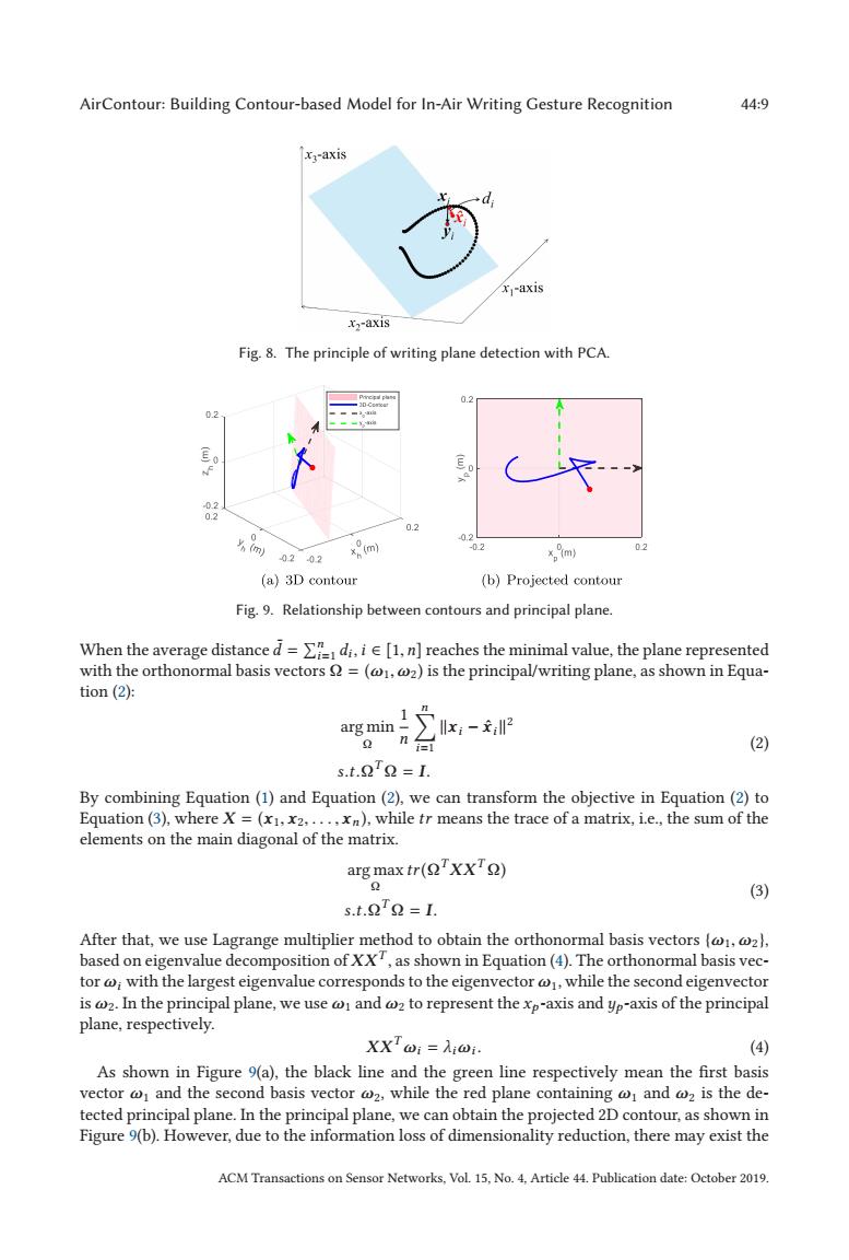
AirContour:Building Contour-based Model for In-Air Writing Gesture Recognition 44:9 xa-axis d xj-axis x2-axis Fig.8.The principle of writing plane detection with PCA. 02 E 4 02 0.2 0.2 0202 xp(m) -02 x。m 02 (a)3 D contour (b)Projected contour Fig.9.Relationship between contours and principal plane. When the average distanced=di.i[1.n]reaches the minimal value,the plane represented with the orthonormal basis vectors =(@1,@2)is the principal/writing plane,as shown in Equa- tion (2): arg min 1x- n司 (2) s.t.22=L. By combining Equation(1)and Equation(2),we can transform the objective in Equation(2)to Equation (3),where X =(x1,x2.....xn),while tr means the trace of a matrix,i.e.,the sum of the elements on the main diagonal of the matrix. arg max tr(Q'XX'Q) (3) s.t.22=L. After that,we use Lagrange multiplier method to obtain the orthonormal basis vectors (@@z), based on eigenvalue decomposition of XX,as shown in Equation(4).The orthonormal basis vec- tor @with the largest eigenvalue corresponds to the eigenvector @while the second eigenvector is @2.In the principal plane,we use and @z to represent the xp-axis and yp-axis of the principal plane,respectively. XXTwi=Ai@i. (4) As shown in Figure 9(a),the black line and the green line respectively mean the first basis vector @1 and the second basis vector @2,while the red plane containing and @z is the de- tected principal plane.In the principal plane,we can obtain the projected 2D contour,as shown in Figure 9(b).However,due to the information loss of dimensionality reduction,there may exist the ACM Transactions on Sensor Networks,Vol.15,No.4.Article 44.Publication date:October 2019.AirContour: Building Contour-based Model for In-Air Writing Gesture Recognition 44:9 Fig. 8. The principle of writing plane detection with PCA. Fig. 9. Relationship between contours and principal plane. When the average distance ¯ d = n i=1 di , i ∈ [1,n] reaches the minimal value, the plane represented with the orthonormal basis vectors Ω = (ω1,ω2) is the principal/writing plane, as shown in Equation (2): arg min Ω 1 n n i=1 xi − xˆi2 s.t.ΩT Ω = I. (2) By combining Equation (1) and Equation (2), we can transform the objective in Equation (2) to Equation (3), where X = (x1, x2,..., xn ), while tr means the trace of a matrix, i.e., the sum of the elements on the main diagonal of the matrix. arg max Ω tr(ΩTXXT Ω) s.t.ΩT Ω = I. (3) After that, we use Lagrange multiplier method to obtain the orthonormal basis vectors {ω1,ω2}, based on eigenvalue decomposition of XXT , as shown in Equation (4). The orthonormal basis vector ωi with the largest eigenvalue corresponds to the eigenvector ω1, while the second eigenvector is ω2. In the principal plane, we use ω1 and ω2 to represent the xp -axis and yp -axis of the principal plane, respectively. XXTωi = λiωi . (4) As shown in Figure 9(a), the black line and the green line respectively mean the first basis vector ω1 and the second basis vector ω2, while the red plane containing ω1 and ω2 is the detected principal plane. In the principal plane, we can obtain the projected 2D contour, as shown in Figure 9(b). However, due to the information loss of dimensionality reduction, there may exist the ACM Transactions on Sensor Networks, Vol. 15, No. 4, Article 44. Publication date: October 2019.����