正在加载图片...
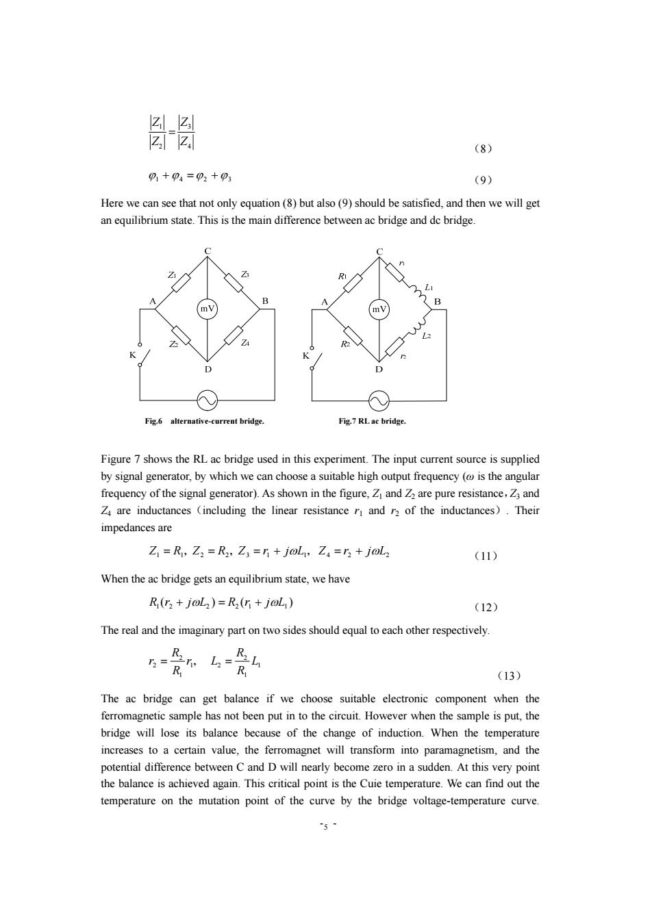
☑_z lzIz.l (8) p1+p4=p2+p3 (9) Here we can see that not only equation(8)but also(9)should be satisfied,and then we will get an equilibrium state.This is the main difference between ac bridge and de bridge. Z B mV R阳 D D Fig.6 alternative-current bridge. Fig.7 RL ac bridge. Figure 7 shows the RL ac bridge used in this experiment.The input current source is supplied by signal generator,by which we can choose a suitable high output frequency (is the angular frequency of the signal generator).As shown in the figure,Z and Z2 are pure resistance,Z3 and Z4 are inductances (including the linear resistance r and r2 of the inductances).Their impedances are Z,=R,Z2=R2,Z3=5+j0L,Z4=53+joL2 (11) When the ac bridge gets an equilibrium state,we have R(r2 joL)=R2(r+joL) (12) The real and the imaginary part on two sides should equal to each other respectively. 3= R R,L R (13) The ac bridge can get balance if we choose suitable electronic component when the ferromagnetic sample has not been put in to the circuit.However when the sample is put,the bridge will lose its balance because of the change of induction.When the temperature increases to a certain value,the ferromagnet will transform into paramagnetism,and the potential difference between C and D will nearly become zero in a sudden.At this very point the balance is achieved again.This critical point is the Cuie temperature.We can find out the temperature on the mutation point of the curve by the bridge voltage-temperature curve.- - 5 4 3 2 1 Z Z Z Z = (8) ϕ1 +ϕ 4 =ϕ 2 +ϕ3 (9) Here we can see that not only equation (8) but also (9) should be satisfied, and then we will get an equilibrium state. This is the main difference between ac bridge and dc bridge. Figure 7 shows the RL ac bridge used in this experiment. The input current source is supplied by signal generator, by which we can choose a suitable high output frequency (ω is the angular frequency of the signal generator). As shown in the figure, Z1 and Z2 are pure resistance,Z3 and Z4 are inductances(including the linear resistance r1 and r2 of the inductances). Their impedances are 1 1 2 2 3 1 1 4 2 2 Z = R, Z = R , Z = r + jωL, Z = r + jωL (11) When the ac bridge gets an equilibrium state, we have ( ) ( ) 1 2 2 2 1 L1 R r + jωL = R r + jω (12) The real and the imaginary part on two sides should equal to each other respectively. 1 1 2 1 2 1 2 2 L R R r L R R r = , = (13) The ac bridge can get balance if we choose suitable electronic component when the ferromagnetic sample has not been put in to the circuit. However when the sample is put, the bridge will lose its balance because of the change of induction. When the temperature increases to a certain value, the ferromagnet will transform into paramagnetism, and the potential difference between C and D will nearly become zero in a sudden. At this very point the balance is achieved again. This critical point is the Cuie temperature. We can find out the temperature on the mutation point of the curve by the bridge voltage-temperature curve. Fig.6 alternative-current bridge. Fig.7 RL ac bridge