正在加载图片...
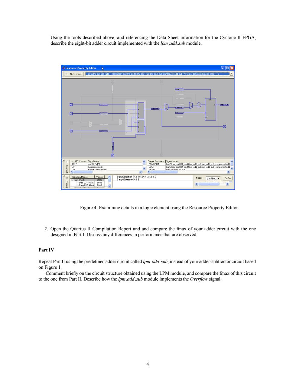
aon习se Figure 4.Examining details in a logic element using the Resource Property Editor. PartIV Comment briefly on the circuit structure obtained using the LPM module,and compare the fmax of this circuit to the one from Part II.Describe how the Ipmadd sub module implements the Overflow signal. gUsing the tools described above, and referencing the Data Sheet information for the Cyclone II FPGA, describe the eight-bit adder circuit implemented with the lpm add sub module. Figure 4. Examining details in a logic element using the Resource Property Editor. 2. Open the Quartus II Compilation Report and and compare the fmax of your adder circuit with the one designed in Part I. Discuss any differences in performance that are observed. Part IV Repeat Part II using the predefined adder circuit called lpm add sub, instead of your adder-subtractor circuit based on Figure 1. Comment briefly on the circuit structure obtained using the LPM module, and compare the fmax of this circuit to the one from Part II. Describe how the lpm add sub module implements the Overflow signal. 4