正在加载图片...
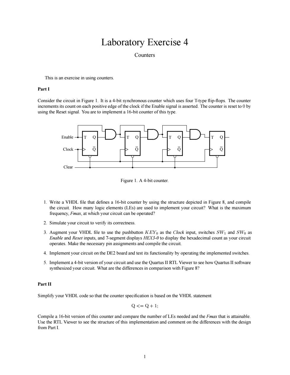
Laboratory Exercise 4 Counters This is an exercise in using counters PartI Consider i Figure 1.It isa4-bit syn s asserte sing the Reset ta 16-bit co ter of thist Figure 1.A4-bit counter. 1.Writea VHDL file that defines a 16-bit frequency.at which your circut can be operated? 2.Simulate your circuit to verify its correctness. 3.Augment your VHDL file to use the pushbutton KEYo as the Clock input,switches SW and SWo as Enable and Reser inputs.and 7-segment displays HEX-0to display the hexadecimal countas your circuit operates.Make the necessary pin assignments and compile the circuit 4.Implement your circuit on the DE2 board and test its functionality by operating the implemented switches Simplify your VHDL code so that the counter specification is based on the VHDL statement Q<=Q+1: r that is s inable from PartI. 1Laboratory Exercise 4 Counters This is an exercise in using counters. Part I Consider the circuit in Figure 1. It is a 4-bit synchronous counter which uses four T-type flip-flops. The counter increments its count on each positive edge of the clock if the Enable signal is asserted. The counter is reset to 0 by using the Reset signal. You are to implement a 16-bit counter of this type. T Q Clock Q T Q Q Enable Clear T Q Q T Q Q Figure 1. A 4-bit counter. 1. Write a VHDL file that defines a 16-bit counter by using the structure depicted in Figure 8, and compile the circuit. How many logic elements (LEs) are used to implement your circuit? What is the maximum frequency, Fmax, at which your circuit can be operated? 2. Simulate your circuit to verify its correctness. 3. Augment your VHDL file to use the pushbutton KEY0 as the Clock input, switches SW1 and SW0 as Enable and Reset inputs, and 7-segment displays HEX3-0 to display the hexadecimal count as your circuit operates. Make the necessary pin assignments and compile the circuit. 4. Implement your circuit on the DE2 board and test its functionality by operating the implemented switches. 5. Implement a 4-bit version of your circuit and use the Quartus II RTL Viewer to see how Quartus II software synthesized your circuit. What are the differences in comparison with Figure 8? Part II Simplify your VHDL code so that the counter specification is based on the VHDL statement Q <= Q + 1; Compile a 16-bit version of this counter and compare the number of LEs needed and the Fmax that is attainable. Use the RTL Viewer to see the structure of this implementation and comment on the differences with the design from Part I. 1