正在加载图片...
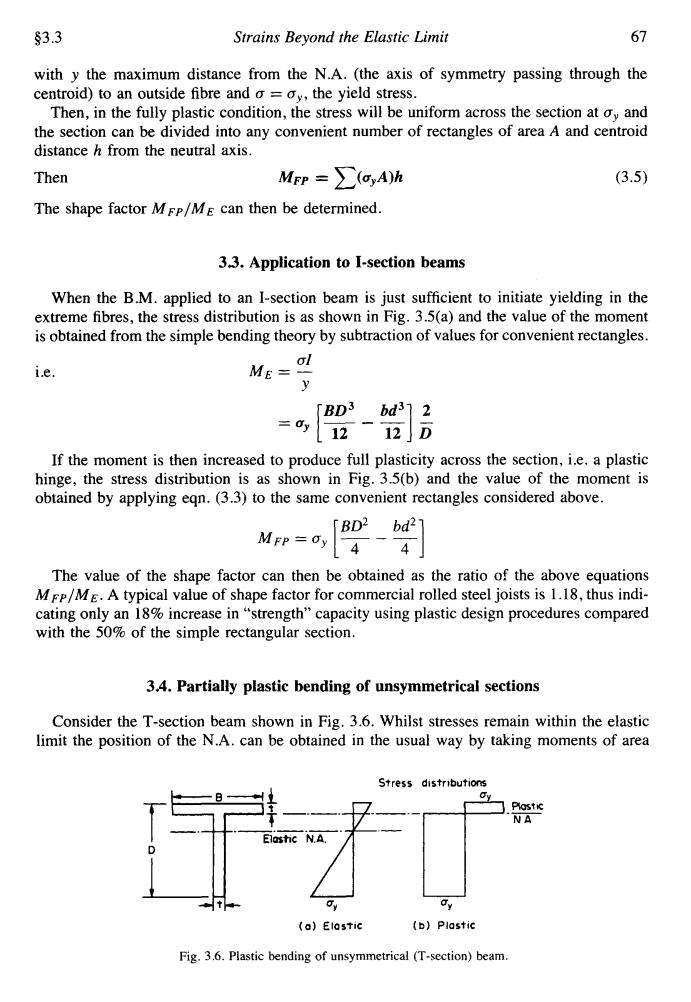
$3.3 Strains Beyond the Elastic Limit 67 with y the maximum distance from the N.A.(the axis of symmetry passing through the centroid)to an outside fibre and o =oy,the yield stress. Then,in the fully plastic condition,the stress will be uniform across the section at oy and the section can be divided into any convenient number of rectangles of area A and centroid distance h from the neutral axis. Then Mrn=∑(a,Ah (3.5) The shape factor MFp/ME can then be determined. 3.3.Application to I-section beams When the B.M.applied to an I-section beam is just sufficient to initiate yielding in the extreme fibres,the stress distribution is as shown in Fig.3.5(a)and the value of the moment is obtained from the simple bending theory by subtraction of values for convenient rectangles. ol ie. ME- y [BD3 bd312 [1212]D If the moment is then increased to produce full plasticity across the section,i.e.a plastic hinge,the stress distribution is as shown in Fig.3.5(b)and the value of the moment is obtained by applying eqn.(3.3)to the same convenient rectangles considered above. BD2 bd27 MFP=Oy 4-4 The value of the shape factor can then be obtained as the ratio of the above equations MFP/ME.A typical value of shape factor for commercial rolled steel joists is 1.18,thus indi- cating only an 18%increase in"strength"capacity using plastic design procedures compared with the 50%of the simple rectangular section. 3.4.Partially plastic bending of unsymmetrical sections Consider the T-section beam shown in Fig.3.6.Whilst stresses remain within the elastic limit the position of the N.A.can be obtained in the usual way by taking moments of area Stress distributions 门Plostic NA (o)Elastic (b)Plastic Fig.3.6.Plastic bending of unsymmetrical (T-section)beam.93.3 Strains Beyond the Elastic Limit 67 with y the maximum distance from the N.A. (the axis of symmetry passing through the centroid) to an outside fibre and (T = oY, the yield stress. Then, in the fully plastic condition, the stress will be uniform across the section at oY and the section can be divided into any convenient number of rectangles of area A and centroid distance h from the neutral axis. Then MFP = x(cyA)h (3.5) The shape factor MFp/ME can then be determined. 33. Application to I-section beams When the B.M. applied to an I-section beam is just sufficient to initiate yielding in the extreme fibres, the stress distribution is as shown in Fig. 3.5(a) and the value of the moment is obtained from the simple bending theory by subtraction of values for convenient rectangles. (TI Y i.e. ME = - BD3 bd3 2 =uy [T - -4 5 MFP ‘Cy [T - -4 If the moment is then increased to produce full plasticity across the section, i.e. a plastic hinge, the stress distribution is as shown in Fig. 33b) and the value of the moment is obtained by applying eqn. (3.3) to the same convenient rectangles considered above. BD2 bd2 The value of the shape factor can then be obtained as the ratio of the above equations MFP/ME. A typical value of shape factor for commercial rolled steel joists is 1.18, thus indicating only an 18% increase in “strength” capacity using plastic design procedures compared with the 50% of the simple rectangular section. 3.4. Partially plastic bending of unsymmetrical sections Consider the T-section beam shown in Fig. 3.6. Whilst stresses remain within the elastic limit the position of the N.A. can be obtained in the usual way by taking moments of area Fig. 3.6. Plastic bending of unsymmetrical (T-section) beam