正在加载图片...
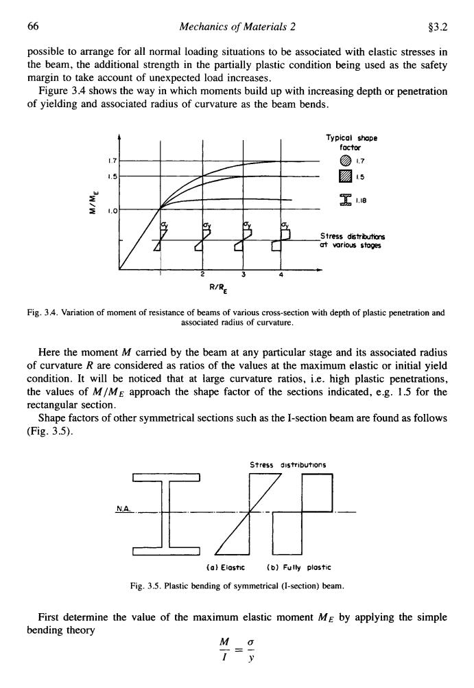
66 Mechanics of Materials 2 §3.2 possible to arrange for all normal loading situations to be associated with elastic stresses in the beam,the additional strength in the partially plastic condition being used as the safety margin to take account of unexpected load increases. Figure 3.4 shows the way in which moments build up with increasing depth or penetration of yielding and associated radius of curvature as the beam bends. Typical shope factor ⑦7 1.5 肠5 写18 1.0 Stress distributions at various stoges R/RE Fig.3.4.Variation of moment of resistance of beams of various cross-section with depth of plastic penetration and associated radius of curvature. Here the moment M carried by the beam at any particular stage and its associated radius of curvature R are considered as ratios of the values at the maximum elastic or initial yield condition.It will be noticed that at large curvature ratios,i.e.high plastic penetrations, the values of M/ME approach the shape factor of the sections indicated,e.g.1.5 for the rectangular section. Shape factors of other symmetrical sections such as the I-section beam are found as follows (Fig.3.5). Stress distributions 王消 A (a)Eiastic (b)Fully plostic Fig.3.5.Plastic bending of symmetrical (I-section)beam. First determine the value of the maximum elastic moment ME by applying the simple bending theory M o 1 y66 Mechanics of Materials 2 93.2 possible to arrange for all normal loading situations to be associated with elastic stresses in the beam, the additional strength in the partially plastic condition being used as the safety margin to take account of unexpected load increases. Figure 3.4 shows the way in which moments build up with increasing depth or penetration of yielding and associated radius of curvature as the beam bends. Typical shape factor 17 @ 1.7 1.5 '5 w 1.18 2, z 1.0 Stress distrbutions vorious stages Fig. 3.4. Variation of moment of resistance of beams of various cross-section with depth of plastic penetration and associated radius of curvature. Here the moment M carried by the beam at any particular stage and its associated radius of curvature R are considered as ratios of the values at the maximum elastic or initial yield condition. It will be noticed that at large curvature ratios, i.e. high plastic penetrations, the values of MIME approach the shape factor of the sections indicated, e.g. 1.5 for the rectangular section. Shape factors of other symmetrical sections such as the I-section beam are found as follows (Fig. 3.5). Stress distributions I1 (01 Elasi~c (b) Fully plostlc Fig. 3.5. Plastic bending of symmetrical (I-section) beam. First determine the value of the maximum elastic moment ME by applying the simple bending theory