正在加载图片...

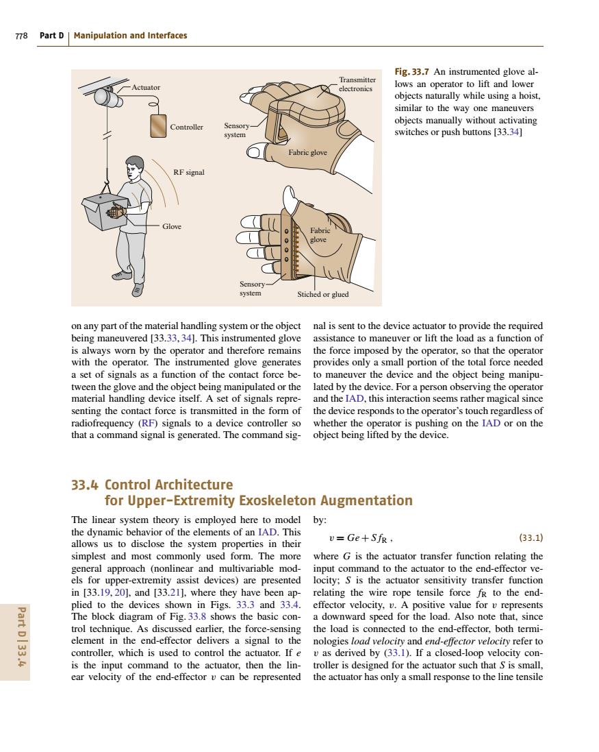
778 Part D Manipulation and Interfaces Fig.33.7 An instrumented glove al- Transmitter Actuator electronics lows an operator to lift and lower objects naturally while using a hoist, similar to the way one maneuvers objects manually without activating ontroller Sensory system switches or push buttons [33.34] Fabric glove RF signal Glove Fabric glove Sensory system Stiched or glued on any part of the material handling system or the object nal is sent to the device actuator to provide the required being maneuvered [33.33,34].This instrumented glove assistance to maneuver or lift the load as a function of is always worn by the operator and therefore remains the force imposed by the operator,so that the operator with the operator.The instrumented glove generates provides only a small portion of the total force needed a set of signals as a function of the contact force be- to maneuver the device and the object being manipu- tween the glove and the object being manipulated or the lated by the device.For a person observing the operator material handling device itself.A set of signals repre- and the IAD,this interaction seems rather magical since senting the contact force is transmitted in the form of the device responds to the operator's touch regardless of radiofrequency (RF)signals to a device controller so whether the operator is pushing on the IAD or on the that a command signal is generated.The command sig- object being lifted by the device. 33.4 Control Architecture for Upper-Extremity Exoskeleton Augmentation The linear system theory is employed here to model by: the dynamic behavior of the elements of an IAD.This allows us to disclose the system properties in their v=Ge+Sfr, (33.1) simplest and most commonly used form.The more where G is the actuator transfer function relating the general approach (nonlinear and multivariable mod-input command to the actuator to the end-effector ve- els for upper-extremity assist devices)are presented locity:S is the actuator sensitivity transfer function in [33.19,20],and [33.21],where they have been ap-relating the wire rope tensile force fr to the end- plied to the devices shown in Figs.33.3 and 33.4.effector velocity,v.A positive value for v represents Part D33.4 The block diagram of Fig.33.8 shows the basic con-a downward speed for the load.Also note that,since trol technique.As discussed earlier,the force-sensing the load is connected to the end-effector,both termi- element in the end-effector delivers a signal to the nologies load velocity and end-effector velocity refer to controller,which is used to control the actuator.If e v as derived by (33.1).If a closed-loop velocity con- is the input command to the actuator,then the lin-troller is designed for the actuator such that S is small, ear velocity of the end-effector v can be represented the actuator has only a small response to the line tensile778 Part D Manipulation and Interfaces RF signal Fabric glove Transmitter electronics Fabric glove Stiched or glued Sensory system Sensory system Glove Controller Actuator Fig. 33.7 An instrumented glove allows an operator to lift and lower objects naturally while using a hoist, similar to the way one maneuvers objects manually without activating switches or push buttons [33.34] on any part of the material handling system or the object being maneuvered [33.33, 34]. This instrumented glove is always worn by the operator and therefore remains with the operator. The instrumented glove generates a set of signals as a function of the contact force between the glove and the object being manipulated or the material handling device itself. A set of signals representing the contact force is transmitted in the form of radiofrequency (RF) signals to a device controller so that a command signal is generated. The command signal is sent to the device actuator to provide the required assistance to maneuver or lift the load as a function of the force imposed by the operator, so that the operator provides only a small portion of the total force needed to maneuver the device and the object being manipulated by the device. For a person observing the operator and the IAD, this interaction seems rather magical since the device responds to the operator’s touch regardless of whether the operator is pushing on the IAD or on the object being lifted by the device. 33.4 Control Architecture for Upper-Extremity Exoskeleton Augmentation The linear system theory is employed here to model the dynamic behavior of the elements of an IAD. This allows us to disclose the system properties in their simplest and most commonly used form. The more general approach (nonlinear and multivariable models for upper-extremity assist devices) are presented in [33.19, 20], and [33.21], where they have been applied to the devices shown in Figs. 33.3 and 33.4. The block diagram of Fig. 33.8 shows the basic control technique. As discussed earlier, the force-sensing element in the end-effector delivers a signal to the controller, which is used to control the actuator. If e is the input command to the actuator, then the linear velocity of the end-effector v can be represented by: v = Ge+ S fR , (33.1) where G is the actuator transfer function relating the input command to the actuator to the end-effector velocity; S is the actuator sensitivity transfer function relating the wire rope tensile force fR to the endeffector velocity, v. A positive value for v represents a downward speed for the load. Also note that, since the load is connected to the end-effector, both terminologies load velocity and end-effector velocity refer to v as derived by (33.1). If a closed-loop velocity controller is designed for the actuator such that S is small, the actuator has only a small response to the line tensile Part D 33.4