正在加载图片...
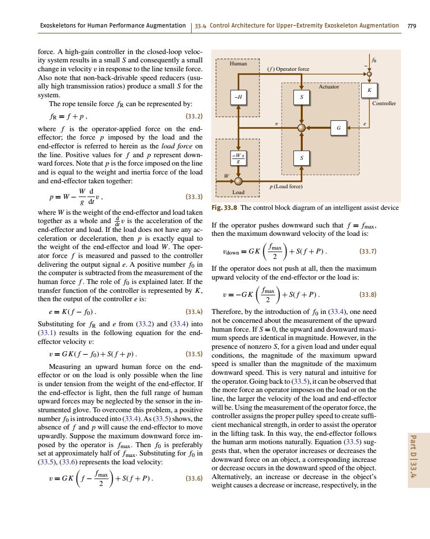
Exoskeletons for Human Performance Augmentation 33.4 Control Architecture for Upper-Extremity Exoskeleton Augmentation 79 force.A high-gain controller in the closed-loop veloc- ity system results in a small S and consequently a small Human change in velocity v in response to the line tensile force. (f)Operator force Also note that non-back-drivable speed reducers (usu- ally high transmission ratios)produce a small S for the Actuator system. The rope tensile force fr can be represented by: Controller fr=f+p, (33.2) where f is the operator-applied force on the end- effector;the force p imposed by the load and the end-effector is referred to herein as the load force on the line.Positive values for f and p represent down- ward forces.Note that p is the force imposed on the line and is equal to the weight and inertia force of the load and end-effector taken together: p(Load force) P=W、 w d Load (33.3) 8d山 Fig.33.8 The control block diagram of an intelligent assist device where W is the weight of the end-effector and load taken together as a whole andis the acceleration of the end-effector and load.If the load does not have any ac- If the operator pushes downward such that f=fmax, celeration or deceleration,then p is exactly equal to then the maximum downward velocity of the load is: the weight of the end-effector and load W.The oper- GK max (33.7) ator force f is measured and passed to the controller Udown 2 S(f+P) delivering the output signal e.A positive number fo in the computer is subtracted from the measurement of the If the operator does not push at all,then the maximum human force f.The role of fo is explained later.If the upward velocity of the end-effector or the load is: transfer function of the controller is represented by K, v=-GK ma +S(f+P) (33.8) then the output of the controller e is: e=K(f-fo). (33.4) Therefore,by the introduction of fo in (33.4),one need Substituting for fr and e from (33.2)and (33.4)into not be concerned about the measurement of the upward (33.1)results in the following equation for the end- human force.If S=0,the upward and downward maxi- effector velocity v: mum speeds are identical in magnitude.However,in the presence of nonzero S,for a given load and under equal v=GK(f-fo)+S(f+p). (33.5) conditions,the magnitude of the maximum upward Measuring an upward human force on the end- speed is smaller than the magnitude of the maximum effector or on the load is only possible when the line downward speed.This is very natural and intuitive for is under tension from the weight of the end-effector.If the operator.Going back to(33.5),it can be observed that the end-effector is light,then the full range of human the more force an operator imposes on the load or on the upward forces may be neglected by the sensor in the in- line,the larger the velocity of the load and end-effector strumented glove.To overcome this problem,a positive will be.Using the measurement of the operator force,the number fo is introduced into(33.4).As(33.5)shows,the controller assigns the proper pulley speed to create suffi- absence of f and p will cause the end-effector to move cient mechanical strength,in order to assist the operator upwardly.Suppose the maximum downward force im- in the lifting task.In this way,the end-effector follows posed by the operator is fmax.Then fo is preferably the human arm motions naturally.Equation (33.5)sug- set at approximately half of fmax.Substituting for fo in gests that,when the operator increases or decreases the Part (33.5),(33.6)represents the load velocity: downward force on an object,a corresponding increase or decrease occurs in the downward speed of the object. 出 u=GK(-)+sf+Pm. (33.6) Alternatively,an increase or decrease in the object's weight causes a decrease or increase,respectively,in theExoskeletons for Human Performance Augmentation 33.4 Control Architecture for Upper-Extremity Exoskeleton Augmentation 779 force. A high-gain controller in the closed-loop velocity system results in a small S and consequently a small change in velocity v in response to the line tensile force. Also note that non-back-drivable speed reducers (usually high transmission ratios) produce a small S for the system. The rope tensile force fR can be represented by: fR = f + p , (33.2) where f is the operator-applied force on the endeffector; the force p imposed by the load and the end-effector is referred to herein as the load force on the line. Positive values for f and p represent downward forces. Note that p is the force imposed on the line and is equal to the weight and inertia force of the load and end-effector taken together: p = W − W g d dt v , (33.3) where W is the weight of the end-effector and load taken together as a whole and d dt v is the acceleration of the end-effector and load. If the load does not have any acceleration or deceleration, then p is exactly equal to the weight of the end-effector and load W. The operator force f is measured and passed to the controller delivering the output signal e. A positive number f0 in the computer is subtracted from the measurement of the human force f . The role of f0 is explained later. If the transfer function of the controller is represented by K, then the output of the controller e is: e = K( f − f0) . (33.4) Substituting for fR and e from (33.2) and (33.4) into (33.1) results in the following equation for the endeffector velocity v: v = GK( f − f0)+ S( f + p) . (33.5) Measuring an upward human force on the endeffector or on the load is only possible when the line is under tension from the weight of the end-effector. If the end-effector is light, then the full range of human upward forces may be neglected by the sensor in the instrumented glove. To overcome this problem, a positive number f0 is introduced into (33.4). As (33.5) shows, the absence of f and p will cause the end-effector to move upwardly. Suppose the maximum downward force imposed by the operator is fmax. Then f0 is preferably set at approximately half of fmax. Substituting for f0 in (33.5), (33.6) represents the load velocity: v = GK f − fmax 2 + S( f + P) . (33.6) p (Load force) Load –W s g S G K f0 –H S W υ e Controller Actuator Human (f ) Operator force – Fig. 33.8 The control block diagram of an intelligent assist device If the operator pushes downward such that f = fmax, then the maximum downward velocity of the load is: vdown = GK fmax 2 + S( f + P) . (33.7) If the operator does not push at all, then the maximum upward velocity of the end-effector or the load is: v = −GK fmax 2 + S( f + P) . (33.8) Therefore, by the introduction of f0 in (33.4), one need not be concerned about the measurement of the upward human force. If S = 0, the upward and downward maximum speeds are identical in magnitude. However, in the presence of nonzero S, for a given load and under equal conditions, the magnitude of the maximum upward speed is smaller than the magnitude of the maximum downward speed. This is very natural and intuitive for the operator. Going back to (33.5), it can be observed that the more force an operator imposes on the load or on the line, the larger the velocity of the load and end-effector will be. Using the measurement of the operator force, the controller assigns the proper pulley speed to create suffi- cient mechanical strength, in order to assist the operator in the lifting task. In this way, the end-effector follows the human arm motions naturally. Equation (33.5) suggests that, when the operator increases or decreases the downward force on an object, a corresponding increase or decrease occurs in the downward speed of the object. Alternatively, an increase or decrease in the object’s weight causes a decrease or increase, respectively, in the Part D 33.4������