正在加载图片...

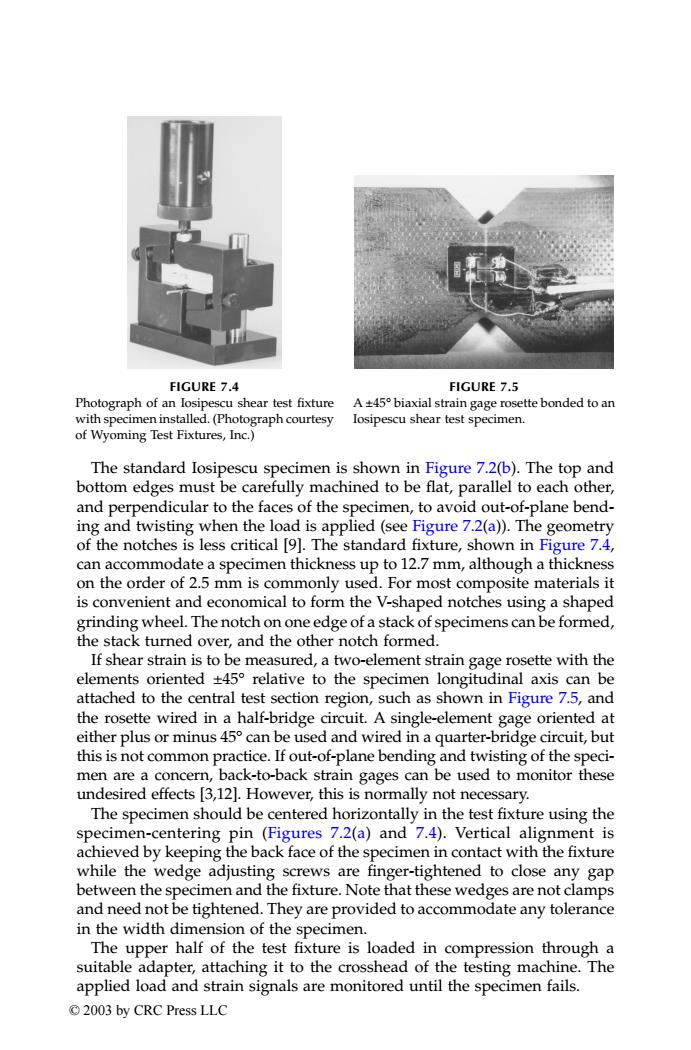
FIGURE 7.4 FIGURE 7.5 Photograph of an losipescu shear test fixture A+45 biaxial strain gage rosette bonded to an with specimen installed.(Photograph courtesy losipescu shear test specimen. of Wyoming Test Fixtures,Inc.) The standard losipescu specimen is shown in Figure 7.2(b).The top and bottom edges must be carefully machined to be flat,parallel to each other, and perpendicular to the faces of the specimen,to avoid out-of-plane bend- ing and twisting when the load is applied(see Figure 7.2(a)).The geometry of the notches is less critical [9].The standard fixture,shown in Figure 7.4, can accommodate a specimen thickness up to 12.7 mm,although a thickness on the order of 2.5 mm is commonly used.For most composite materials it is convenient and economical to form the V-shaped notches using a shaped grinding wheel.The notch on one edge of a stack of specimens can be formed, the stack turned over,and the other notch formed. If shear strain is to be measured,a two-element strain gage rosette with the elements oriented +45 relative to the specimen longitudinal axis can be attached to the central test section region,such as shown in Figure 7.5,and the rosette wired in a half-bridge circuit.A single-element gage oriented at either plus or minus 45 can be used and wired in a quarter-bridge circuit,but this is not common practice.If out-of-plane bending and twisting of the speci- men are a concern,back-to-back strain gages can be used to monitor these undesired effects [3,12].However,this is normally not necessary. The specimen should be centered horizontally in the test fixture using the specimen-centering pin (Figures 7.2(a)and 7.4).Vertical alignment is achieved by keeping the back face of the specimen in contact with the fixture while the wedge adjusting screws are finger-tightened to close any gap between the specimen and the fixture.Note that these wedges are not clamps and need not be tightened.They are provided to accommodate any tolerance in the width dimension of the specimen. The upper half of the test fixture is loaded in compression through a suitable adapter,attaching it to the crosshead of the testing machine.The applied load and strain signals are monitored until the specimen fails. ©2003 by CRC Press LLCThe standard Iosipescu specimen is shown in Figure 7.2(b). The top and bottom edges must be carefully machined to be flat, parallel to each other, and perpendicular to the faces of the specimen, to avoid out-of-plane bending and twisting when the load is applied (see Figure 7.2(a)). The geometry of the notches is less critical [9]. The standard fixture, shown in Figure 7.4, can accommodate a specimen thickness up to 12.7 mm, although a thickness on the order of 2.5 mm is commonly used. For most composite materials it is convenient and economical to form the V-shaped notches using a shaped grinding wheel. The notch on one edge of a stack of specimens can be formed, the stack turned over, and the other notch formed. If shear strain is to be measured, a two-element strain gage rosette with the elements oriented ±45° relative to the specimen longitudinal axis can be attached to the central test section region, such as shown in Figure 7.5, and the rosette wired in a half-bridge circuit. A single-element gage oriented at either plus or minus 45° can be used and wired in a quarter-bridge circuit, but this is not common practice. If out-of-plane bending and twisting of the specimen are a concern, back-to-back strain gages can be used to monitor these undesired effects [3,12]. However, this is normally not necessary. The specimen should be centered horizontally in the test fixture using the specimen-centering pin (Figures 7.2(a) and 7.4). Vertical alignment is achieved by keeping the back face of the specimen in contact with the fixture while the wedge adjusting screws are finger-tightened to close any gap between the specimen and the fixture. Note that these wedges are not clamps and need not be tightened. They are provided to accommodate any tolerance in the width dimension of the specimen. The upper half of the test fixture is loaded in compression through a suitable adapter, attaching it to the crosshead of the testing machine. The applied load and strain signals are monitored until the specimen fails. FIGURE 7.4 Photograph of an Iosipescu shear test fixture with specimen installed. (Photograph courtesy of Wyoming Test Fixtures, Inc.) FIGURE 7.5 A ±45° biaxial strain gage rosette bonded to an Iosipescu shear test specimen. TX001_ch07_Frame Page 108 Saturday, September 21, 2002 4:58 AM © 2003 by CRC Press LLC