正在加载图片...

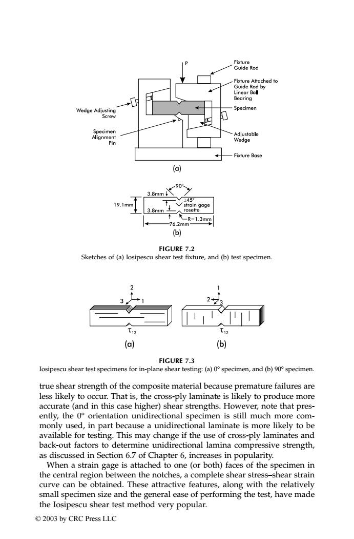
Fixture Guide Rod Fixture Attached to Guide Rod by Linear Ball Bearing Wedge Adjusting Specimen Screw 0 Specimen Adjustable Alignment Pin Wedge Fixture Base (a) 90° 3.8mm↓ ±45 19,1mm Vstrain gage 3.8mm± rosette 无R=1.3mm 76.2mm (6) FIGURE 7.2 Sketches of(a)losipescu shear test fixture,and(b)test specimen. 412 (a) (b) FIGURE 7.3 losipescu shear test specimens for in-plane shear testing:(a)0 specimen,and (b)90 specimen. true shear strength of the composite material because premature failures are less likely to occur.That is,the cross-ply laminate is likely to produce more accurate(and in this case higher)shear strengths.However,note that pres- ently,the 0 orientation unidirectional specimen is still much more com- monly used,in part because a unidirectional laminate is more likely to be available for testing.This may change if the use of cross-ply laminates and back-out factors to determine unidirectional lamina compressive strength, as discussed in Section 6.7 of Chapter 6,increases in popularity. When a strain gage is attached to one(or both)faces of the specimen in the central region between the notches,a complete shear stress-shear strain curve can be obtained.These attractive features,along with the relatively small specimen size and the general ease of performing the test,have made the losipescu shear test method very popular. ©2003 by CRC Press LLCtrue shear strength of the composite material because premature failures are less likely to occur. That is, the cross-ply laminate is likely to produce more accurate (and in this case higher) shear strengths. However, note that presently, the 0° orientation unidirectional specimen is still much more commonly used, in part because a unidirectional laminate is more likely to be available for testing. This may change if the use of cross-ply laminates and back-out factors to determine unidirectional lamina compressive strength, as discussed in Section 6.7 of Chapter 6, increases in popularity. When a strain gage is attached to one (or both) faces of the specimen in the central region between the notches, a complete shear stress–shear strain curve can be obtained. These attractive features, along with the relatively small specimen size and the general ease of performing the test, have made the Iosipescu shear test method very popular. FIGURE 7.2 Sketches of (a) Iosipescu shear test fixture, and (b) test specimen. FIGURE 7.3 Iosipescu shear test specimens for in-plane shear testing: (a) 0° specimen, and (b) 90° specimen. TX001_ch07_Frame Page 107 Saturday, September 21, 2002 4:58 AM © 2003 by CRC Press LLC