正在加载图片...
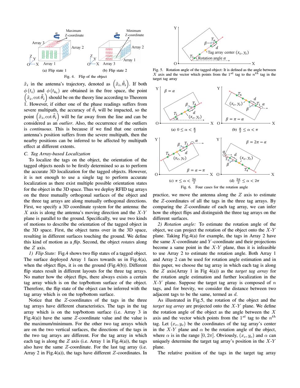
Maximum Minimum Z-coordinate Z-coordinate Array 3 Array 2 Array 2 Tag array center (xc,ye) Array I 2 Rotation angle..◆ Array I -X Array 3 0 -X (a)Flip state 1 (b)Flip state 2 Fig.5.Rotation angle of the tagged object:It is defined as the angle between Fig.4.Flip of the object Xaxis and the vector which points from the 1st tag to then tag in the target tag array in the antenna's trajectory,denoted as ()If both Y (ti)and (t)are obtained in the free space,the point B=a cotshould be on the theory line according to Theorem T4 1.However,if either one of the phase readings suffers from (xc,yc) Ti a severe multipath,the accuracy of will be impacted,so the d point (cot will be far away from the line and can be (xe,ye) B=π- considered as an outlier.Also,the occurrence of the outliers 0 is continuous.This is because if we find that one certain a)0≤a< (b)5≤a<T antenna's position suffers from the severe multipath,then the nearby positions can be inferred to be affected by multipath T B=2π-a effect at different extents. C.Tag Array-based Localization d To localize the tags on the object,the orientation of the (Xc,yc) (xc,yc) tagged objects needs to be firstly determined so as to perform the accurate 3D localization for the tagged objects.However, B=-π X O it is not enough to use a single tag to perform accurate localization as there exist multiple possible orientation states ⊙r≤a<罗 (d要≤a<2m for the object in the 3D space.Thus we deploy RFID tag arrays Fig.6.Four cases for the rotation angle on the three mutually orthogonal surfaces of the object and practice,we move the antenna along the Z axis to estimate the three tag arrays are along mutually orthogonal directions. the Z-coordinates of all the tags in the three tag arrays.By First,we specify a 3D coordinate system for the antenna:the comparing the Z-coordinate of each tag array,we can infer X axis is along the antenna's moving direction and the X-Y how the object flips and distinguish the three tag arrays on the plane is parallel to the ground.Specifically,we use two kinds different surfaces. of motions to describe the orientation of the tagged object in 2)Rotation angle:To estimate the rotation angle of the the 3D space.First,the object turns over in the 3D space, object,we can project the rotation of the object onto the X-Y resulting in different surfaces touching the ground.We define plane.Taking Fig.4(a)for example,the tags in Array 2 have this kind of motion as a flip.Second,the object rotates along the same X-coordinate and Y-coordinate and their projections the Z axis. become a same point in the X-Y plane,thus it is infeasible 1)Flip State:Fig.4 shows two flip states of a tagged object.to use Array 2 to estimate the rotation angle.Both Array 1 The surface deployed Array 1 faces towards us in Fig.4(a),and Array 2 can be used for rotation angle estimation and in when the object flips,it is on the ground(Fig.4(b)).Different this paper,we choose the tag array in which each tag is along flip states result in different layouts for the three tag arrays.the Z axis(Array 1 in Fig 4(a))as the target tag array for No matter how the object flips,there always exists a certain the rotation angle estimation and further localization in the tag array which is on the top/bottom surface of the object.X-Y plane.Suppose the target tag array is composed of n Therefore,the flip state of the object can be inferred with the tags,and for brevity,we consider the distance between two tag array which is on the top/bottom surface. adjacent tags to be the same,termed as d. Notice that the Z-coordinates of the tags in the three As illustrated in Fig.5,the rotation of the object and the tag arrays have different characteristics.The tags in the tag target tag array are projected onto the X-Y plane.We define array which is on the top/bottom surface (i.e.Array 3 in the rotation angle of the object as the angle between theX Fig.4(a))have the same Z-coordinate value and the value is axis and the vector which points from the 1st tag to the nth the maximum/minimum.For the other two tag arrays which tag.Let (c,yc)be the coordinates of the tag array's center are on the two vertical surfaces,the directions of the tags inin the X-Y plane and a be the rotation angle of the object, the two tag arrays are different.For the tag array in which where a is in the range [0,2].Obviously,(,yc)and o can each tag is along the Z axis(i.e.Array 1 in Fig.4(a)),the tags uniquely determine the target tag array's position in the X-Y also have the same Z-coordinate.For the last tag array (i.e.plane. Array 2 in Fig.4(a)),the tags have different 2-coordinates.In The relative position of the tags in the target tag arrayArray 1 Array 3 X Y Z α Maximum Z-coordinate Array 2 O (a) Flip state 1 Array 1 Array 2 α Minimum Z-coordinate X Array 3 Y Z O (b) Flip state 2 Fig. 4. Flip of the object x˜i in the antenna’s trajectory, denoted as ( x˜i , ˜θi ) . If both ϕ (ti) and ϕ (tki ( ) are obtained in the free space, the point x˜i , cot ˜θi ) should be on the theory line according to Theorem 1. However, if either one of the phase readings suffers from severe multipath, the accuracy of ˜θi will be impacted, so the point ( x˜i , cot ˜θi ) will be far away from the line and can be considered as an outlier. Also, the occurrence of the outliers is continuous. This is because if we find that one certain antenna’s position suffers from the severe multipath, then the nearby positions can be inferred to be affected by multipath effect at different extents. C. Tag Array-based Localization To localize the tags on the object, the orientation of the tagged objects needs to be firstly determined so as to perform the accurate 3D localization for the tagged objects. However, it is not enough to use a single tag to perform accurate localization as there exist multiple possible orientation states for the object in the 3D space. Thus we deploy RFID tag arrays on the three mutually orthogonal surfaces of the object and the three tag arrays are along mutually orthogonal directions. First, we specify a 3D coordinate system for the antenna: the X axis is along the antenna’s moving direction and the X-Y plane is parallel to the ground. Specifically, we use two kinds of motions to describe the orientation of the tagged object in the 3D space. First, the object turns over in the 3D space, resulting in different surfaces touching the ground. We define this kind of motion as a flip. Second, the object rotates along the Z axis. 1) Flip State: Fig.4 shows two flip states of a tagged object. The surface deployed Array 1 faces towards us in Fig.4(a), when the object flips, it is on the ground (Fig.4(b)). Different flip states result in different layouts for the three tag arrays. No matter how the object flips, there always exists a certain tag array which is on the top/bottom surface of the object. Therefore, the flip state of the object can be inferred with the tag array which is on the top/bottom surface. Notice that the Z-coordinates of the tags in the three tag arrays have different characteristics. The tags in the tag array which is on the top/bottom surface (i.e. Array 3 in Fig.4(a)) have the same Z-coordinate value and the value is the maximum/minimum. For the other two tag arrays which are on the two vertical surfaces, the directions of the tags in the two tag arrays are different. For the tag array in which each tag is along the Z axis (i.e. Array 1 in Fig.4(a)), the tags also have the same Z-coordinate. For the last tag array (i.e. Array 2 in Fig.4(a)), the tags have different Z-coordinates. In Rotation angle ߙ Tag array center ሺݔ ሻݕ , ܶଵ X Y O ܶ ߚ ݀ Fig. 5. Rotation angle of the tagged object: It is defined as the angle between X axis and the vector which points from the 1 st tag to the n th tag in the target tag array ߙ ߚ ݀ ݔሺ ሻݕ , ߙ ൌ ߚ O X ܶଵ ܶସ Y (a) 0 ≤ α < π 2 ߙ ߚ ݀ ݔሺ ሻݕ , ߙ െ ߨ ൌ ߚ X ܶଵ ܶସ Y O (b) π 2 ≤ α < π ߙ ߚ ݀ ݔሺ ሻݕ , X Y ܶସ ܶଵ ߨ െ ߙ ൌ ߚ O (c) π ≤ α < 3π 2 ߙ ߚ ݀ ݔሺ ሻݕ , X ܶସ ܶଵ Y ߙ െ ߨʹ ൌ ߚ O (d) 3π 2 ≤ α < 2π Fig. 6. Four cases for the rotation angle practice, we move the antenna along the Z axis to estimate the Z-coordinates of all the tags in the three tag arrays. By comparing the Z-coordinate of each tag array, we can infer how the object flips and distinguish the three tag arrays on the different surfaces. 2) Rotation angle: To estimate the rotation angle of the object, we can project the rotation of the object onto the X-Y plane. Taking Fig.4(a) for example, the tags in Array 2 have the same X-coordinate and Y -coordinate and their projections become a same point in the X-Y plane, thus it is infeasible to use Array 2 to estimate the rotation angle. Both Array 1 and Array 2 can be used for rotation angle estimation and in this paper, we choose the tag array in which each tag is along the Z axis(Array 1 in Fig 4(a)) as the target tag array for the rotation angle estimation and further localization in the X-Y plane. Suppose the target tag array is composed of n tags, and for brevity, we consider the distance between two adjacent tags to be the same, termed as d. As illustrated in Fig.5, the rotation of the object and the target tag array are projected onto the X-Y plane. We define the rotation angle of the object as the angle between the X axis and the vector which points from the 1 st tag to the n th tag. Let (xc, yc) be the coordinates of the tag array’s center in the X-Y plane and α be the rotation angle of the object, where α is in the range [0, 2π]. Obviously, (xc, yc) and α can uniquely determine the target tag array’s position in the X-Y plane. The relative position of the tags in the target tag array