正在加载图片...
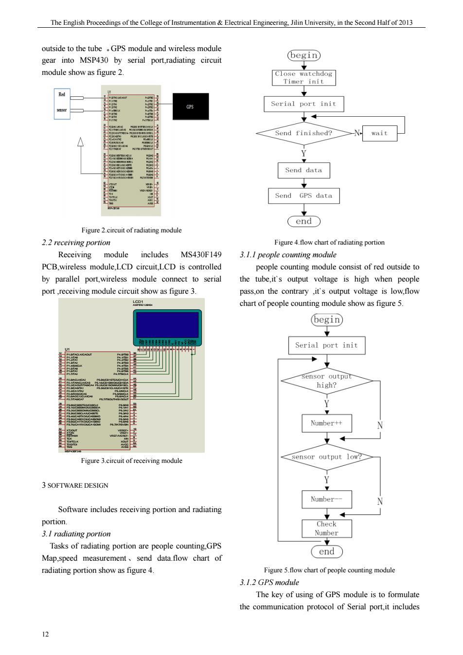
The English Proceedings of the College of Instrumentation Electrical Engineering.Jilin University,in the Second Half of 2013 outside to the tubePS module and wireless modul gear into MSP430 by serial port,radiating circuit begin module show as figure 2. Serial port init Send finished?N wait Send data Send GPS data Figure of radiating module 2.2 receiving portion Figure chart portior Receiving module includes MS430F149 3.1.I people counting module PCB.wireless module LCD circuit.LCD is controlled people counting module consist of red outside to by parallel port,wireless module connect to serial the tube it's output voltage is high when people ort,module circuit show as figure 3. pass on the contrary it's output voltage is low flow chart of people counting module show as figure5. begin Serial port init ens Number++ Figure 3.circuit of receiving module sensor output low? 3 SOFTWARE DESIGN umber-一 Software includes receiving portion and radiating portion 3.I radiating portion Tasks of radiating portion are people counting GPS send data flow chart of end Map,speed measur hart of people ounting n 3.1.2 GPS module The key of using of GPS module is to formulate the communication protocol of Serial port,it includes 12 期 The English Proceedings of the College of Instrumentation & Electrical Engineering, Jilin University, in the Second Half of 2013 12 outside to the tube 。GPS module and wireless module gear into MSP430 by serial port,radiating circuit module show as figure 2. Figure 2.circuit of radiating module 2.2 receiving portion Receiving module includes MS430F149 PCB,wireless module,LCD circuit,LCD is controlled by parallel port,wireless module connect to serial port ,receiving module circuit show as figure 3. P2.5/ROSC/CA5 25 P2.4/CA1/TA2 24 P2.3/CA0/TA1 23 P2.2/CAOUT/TA0/CA4 22 P2.1/TAINCLK/CA3 21 P2.0/ACLK/CA2 20 P1.2/TA1 14 P1.1/TA0 13 P1.0/TACLK/CAOUT 12 P1.3/TA2 15 P1.4/SMCLK 16 P1.7/TA2 19 P1.6/TA1 18 P1.5/TA0 17 P2.6/ADC12CLK/CA6 26 P2.7/TA0/CA7 27 P3.0/UCB0STE/UCA0CLK 28 P3.1/UCB0SIMO/UCB0SDA 29 P3.2/UCB0SOMI/UCB0SCL 30 P3.3/UCB0CLK/UCA0STE 31 P3.4/UCA0TXD/UCA0SIMO 32 P3.5/UCA0RXD/UCA0SOMI 33 P3.6/UCA1TXD/UCA1SIMO 34 P3.7/UCA1RXD/UCA1SOMI 35 P4.5/TB5 41 P4.4/TB4 40 P4.3/TB3 39 P4.2/TB2 38 P4.1/TB1 37 P4.0/TB0 36 P4.6/TB6 42 P4.7/TBCLK 43 AVCC 64 AVSS 62 P5.0/UCB1STE/UCA1CLK 44 P5.1/UCB1SIMO/UCB1SDA 45 P5.2/UCB1SOMI/UCB1SCL 46 P5.3/UCB1CLK/UCA1STE 47 P5.4/MCLK 48 P5.5/SMCLK 49 P5.6/ACLK 50 P5.7/TBOUTH/SVSOUT 51 P6.0/A0 59 P6.1/A1 60 P6.2/A2 61 P6.3/A3 2 P6.4/A4 3 P6.5/A5 4 P6.6/A6 5 P6.7/A7/SVSIN 6 XT2OUT 52 XT2IN 53 RST/NMI 58 TCK 57 TDI/TCLK 55 TMS 56 VEREF+ 10 VREF+ 7 XIN 8 XOUT 9 TDO/TDI 54 VREF-/VEREF- 11 U1 MSP430F249 CS1 1 CS2 2 GND 3 VCC 4 V0 5 RS 6 R/W 7 E 8 DB0 9 DB1 10 DB2 11 DB3 12 DB4 13 DB5 14 DB6 15 DB7 16 RST 17 -Vout 18 LCD1 AMPIRE128X64 Figure 3.circuit of receiving module 3 SOFTWARE DESIGN Software includes receiving portion and radiating portion. 3.1 radiating portion Tasks of radiating portion are people counting,GPS Map,speed measurement、send data.flow chart of radiating portion show as figure 4. Figure 4.flow chart of radiating portion 3.1.1 people counting module people counting module consist of red outside to the tube,it`s output voltage is high when people pass,on the contrary ,it`s output voltage is low,flow chart of people counting module show as figure 5. Figure 5.flow chart of people counting module 3.1.2 GPS module The key of using of GPS module is to formulate the communication protocol of Serial port,it includes