正在加载图片...

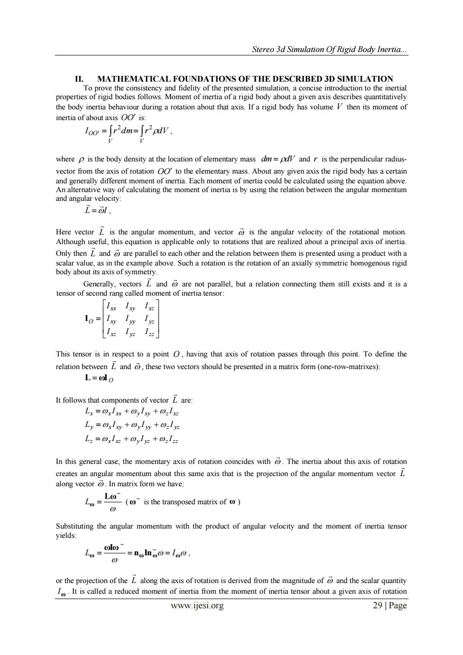
Stereo 3d Simulation Of Rigid Body Inertia... II.MATHEMATICAL FOUNDATIONS OF THE DESCRIBED 3D SIMULATION To prove the consistency and fidelity of the presented simulation,a concise introduction to the inertial properties of rigid bodies follows.Moment of inertia of a rigid body about a given axis describes quantitatively the body inertia behaviour during a rotation about that axis.If a rigid body has volume V then its moment of inertia of about axis OO'is: where p is the body density at the location of elementary mass dm=pdl and r is the perpendicular radius- vector from the axis of rotation OO'to the elementary mass.About any given axis the rigid body has a certain and generally different moment of inertia.Each moment of inertia could be calculated using the equation above. An alternative way of calculating the moment of inertia is by using the relation between the angular momentum and angular velocity: i=, Here vector L is the angular momentum,and vector is the angular velocity of the rotational motion. Although useful,this equation is applicable only to rotations that are realized about a principal axis of inertia. Only then L and are parallel to each other and the relation between them is presented using a product with a scalar value,as in the example above.Such a rotation is the rotation of an axially symmetric homogenous rigid body about its axis of symmetry. Generally,vectors L and are not parallel,but a relation connecting them still exists and it is a tensor of second rang called moment of inertia tensor: 1o= y 1 1 1 This tensor is in respect to a point O,having that axis of rotation passes through this point.To define the relation between L and these two vectors should be presented in a matrix form(one-row-matrixes): L=@lo It follows that components of vector L are: Lx=@xlxx+oylxy+0I Ly=@xlxy+@ylw+ly L:=@xlx+yly+01- In this general case,the momentary axis of rotation coincides with The inertia about this axis of rotation creates an angular momentum about this same axis that is the projection of the angular momentum vector L along vector In matrix form we have: LO Lo=- -(0 is the transposed matrix of c Substituting the angular momentum with the product of angular velocity and the moment of inertia tensor yields: olo Lo= -=noIn@=1o0, 0 or the projection of the L along the axis of rotation is derived from the magnitude of and the scalar quantity I.It is called a reduced moment of inertia from the moment of inertia tensor about a given axis of rotation www.ijesi.org 29 PageStereo 3d Simulation Of Rigid Body Inertia... www.ijesi.org 29 | Page II. MATHEMATICAL FOUNDATIONS OF THE DESCRIBED 3D SIMULATION To prove the consistency and fidelity of the presented simulation, a concise introduction to the inertial properties of rigid bodies follows. Moment of inertia of a rigid body about a given axis describes quantitatively the body inertia behaviour during a rotation about that axis. If a rigid body has volume V then its moment of inertia of about axis OO is: V V IOO r dm r dV 2 2 , where is the body density at the location of elementary mass dm dV and r is the perpendicular radiusvector from the axis of rotation OO to the elementary mass. About any given axis the rigid body has a certain and generally different moment of inertia. Each moment of inertia could be calculated using the equation above. An alternative way of calculating the moment of inertia is by using the relation between the angular momentum and angular velocity: L I , Here vector L is the angular momentum, and vector is the angular velocity of the rotational motion. Although useful, this equation is applicable only to rotations that are realized about a principal axis of inertia. Only then L and are parallel to each other and the relation between them is presented using a product with a scalar value, as in the example above. Such a rotation is the rotation of an axially symmetric homogenous rigid body about its axis of symmetry. Generally, vectors L and are not parallel, but a relation connecting them still exists and it is a tensor of second rang called moment of inertia tensor: xz yz zz xy yy yz xx xy xz O I I I I I I I I I I This tensor is in respect to a point O , having that axis of rotation passes through this point. To define the relation between L and , these two vectors should be presented in a matrix form (one-row-matrixes): L ωI O It follows that components of vector L are: x x xx y xy z xz L I I I y x xy y yy z yz L I I I z x xz y yz z zz L I I I In this general case, the momentary axis of rotation coincides with . The inertia about this axis of rotation creates an angular momentum about this same axis that is the projection of the angular momentum vector L along vector . In matrix form we have: ~ Lω Lω ( ~ ω is the transposed matrix of ω ) Substituting the angular momentum with the product of angular velocity and the moment of inertia tensor yields: ω nωInω ω ωIω L I ~ ~ , or the projection of the L along the axis of rotation is derived from the magnitude of and the scalar quantity Iω . It is called a reduced moment of inertia from the moment of inertia tensor about a given axis of rotation