正在加载图片...
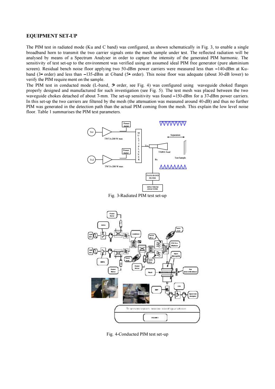
EQUIPMENT SET-UP broadband horn to transmit the two crier signals onto the mesh verify the PIM require ment on the sample. are floor.Table 1 summarises the PIM test parameters. WWWW △△M△△ Fig3-Radiated PIM test set-up a7 0-区图早 E0-阁 Fig4-Conducted PIM test set-upEQUIPMENT SET-UP The PIM test in radiated mode (Ku and C band) was configured, as shown schematically in Fig. 3, to enable a single broadband horn to transmit the two carrier signals onto the mesh sample under test. The reflected radiation will be analysed by means of a Spectrum Analyser in order to capture the intensity of the generated PIM harmonic. The sensitivity of test set-up to the environment was verified using an assumed ideal PIM free generator (pure aluminium screen). Residual bench noise floor applying two 50-dBm power carriers were measured less than -140-dBm at Kuband (3rd order) and less than -135-dBm at C-band (5th order). This noise floor was adequate (about 30-dB lower) to verify the PIM require ment on the sample. The PIM test in conducted mode (L-band, 5th order, see Fig. 4) was configured using waveguide choked flanges properly designed and manufactured for such investigation (see Fig. 5). The test mesh was placed between the two waveguide chokes detached of about 7-mm. The set-up sensitivity was found -150-dBm for a 37-dBm power carriers. In this set-up the two carriers are filtered by the mesh (the attenuation was measured around 40-dB) and thus no further PIM was generated in the detection path than the actual PIM coming from the mesh. This explain the low level noise floor. Table 1 summarises the PIM test parameters. Tx1 Tx2 Power meter M U L T I P L E X E R SPECTRUM ANALYZER TWTA-200 W max TWTA-200 W max Rx Tx Test Sample Separation PASS-BAND FILTER TX/RX Feed Power meter Fig. 3-Radiated PIM test set-up Fig. 4-Conducted PIM test set-up