正在加载图片...
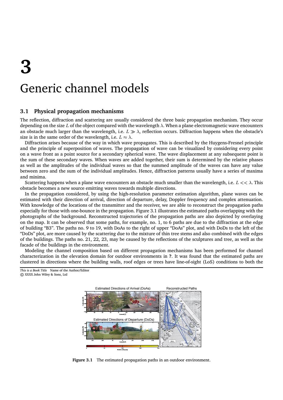
3 Generic channel models 3.1 Physical propagation mechanisms The reflection,diffraction and scattering are usually considered the three basic gation mechanism.they occu an obstacle much larger than the w e.,reflection occurs.Diffraction happens when the obstacle's Diffraction arises because of the way in which wave propagates.This is described by the Huygens-Fresnel principle and the principle of waves.Th he propaga n of wth e can be Visualized by consi ing every poin the sum of these secondary waves.When waves are added together,their sum is determined by the relative phases and minima. agation considered,by using the high-r esolution parameter estimation algorithm plane waves can be val,of.delay,Doppler queny and complex especially for those with one-bouncen the pro tion.Figure 3.1 illustrates the estimated aths o photographs of th rajectories of the propagation paths are also d picted by o and with DoDs to the left of the sed by th a ade of thebuildings in the environment. Modeling the channel based on different mechanisms has where the uoofhave the constructed Paths Estimated Dire of Departure oD) Figure 3.1 The estimated propagation paths in an outdoor environment.3 Generic channel models 3.1 Physical propagation mechanisms The reflection, diffraction and scattering are usually considered the three basic propagation mechanism. They occur depending on the size L of the object compared with the wavelength λ. When a plane electromagnetic wave encounters an obstacle much larger than the wavelength, i.e. L ≫ λ, reflection occurs. Diffraction happens when the obstacle’s size is in the same order of the wavelength, i.e. L ≈ λ. Diffraction arises because of the way in which wave propagates. This is described by the Huygens-Fresnel principle and the principle of superposition of waves. The propagation of wave can be visualized by considering every point on a wave front as a point source for a secondary spherical wave. The wave displacement at any subsequent point is the sum of these secondary waves. When waves are added together, their sum is determined by the relative phases as well as the amplitudes of the individual waves so that the summed amplitude of the waves can have any value between zero and the sum of the individual amplitudes. Hence, diffraction patterns usually have a series of maxima and minima. Scattering happens when a plane wave encounters an obstacle much smaller than the wavelength, i.e. L << λ. This obstacle becomes a new source emitting waves towards multiple directions. In the propagation considered, by using the high-resolution parameter estimation algorithm, plane waves can be estimated with their direction of arrival, direction of departure, delay, Doppler frequency and complex attenuation. With knowledge of the locations of the transmitter and the receiver, we are able to reconstruct the propagation paths especially for those with one-bounce in the propagation. Figure 3.1 illustrates the estimated paths overlapping with the photographs of the background. Reconstructed trajectories of the propagation paths are also depicted by overlaying on the map. It can be observed that some paths, for example, no. 1, to 6 paths are due to the diffraction at the edge of building “B3”. The paths no. 9 to 19, with DoAs to the right of upper “DoAs” plot, and with DoDs to the left of the “DoDs” plot, are more caused by the scattering due to the mixture of thin tree stems and also combined with the edges of the buildings. The paths no. 21, 22, 23, may be caused by the reflections of the sculptures and tree, as well as the facade of the buildings in the environment. Modeling the channel composition based on different propagation mechanisms has been performed for channel characterization in the elevation domain for outdoor environments in ?. It was found that the estimated paths are clustered in directions where the building walls, roof edges or trees have line-of-sight (LoS) conditions to both the This is a Book Title Name of the Author/Editor c XXXX John Wiley & Sons, Ltd E Estimated Directions of Arrival (DoAs) Reconstructed Paths Estimated Directions of Departure (DoDs) 25 24 23 22 21 20 19 17 18 16 15 14 13 12 11 10 9 8 5 7 6 4 3 2 1 Azimuth [°] Coelevation [°] 40 30 20 10 0 -10 -20 -30 -40 -50 85 90 95 100 105 110 25 24 23 22 21 20 19 18 17 16 15 14 13 12 11 10 98 674532 1 Azimuth [°] Coelevation [°] 150 100 50 0 -50 -100 -150 60 80 100 120 Relative delay [ns] 0 82 164 246 329 23 22 21 12 25 24 7 Tx 2 1 15 6 5 10 3 4 13 11 16 17 Rx 9 18 14 8 19 20 Figure 3.1 The estimated propagation paths in an outdoor environment