正在加载图片...
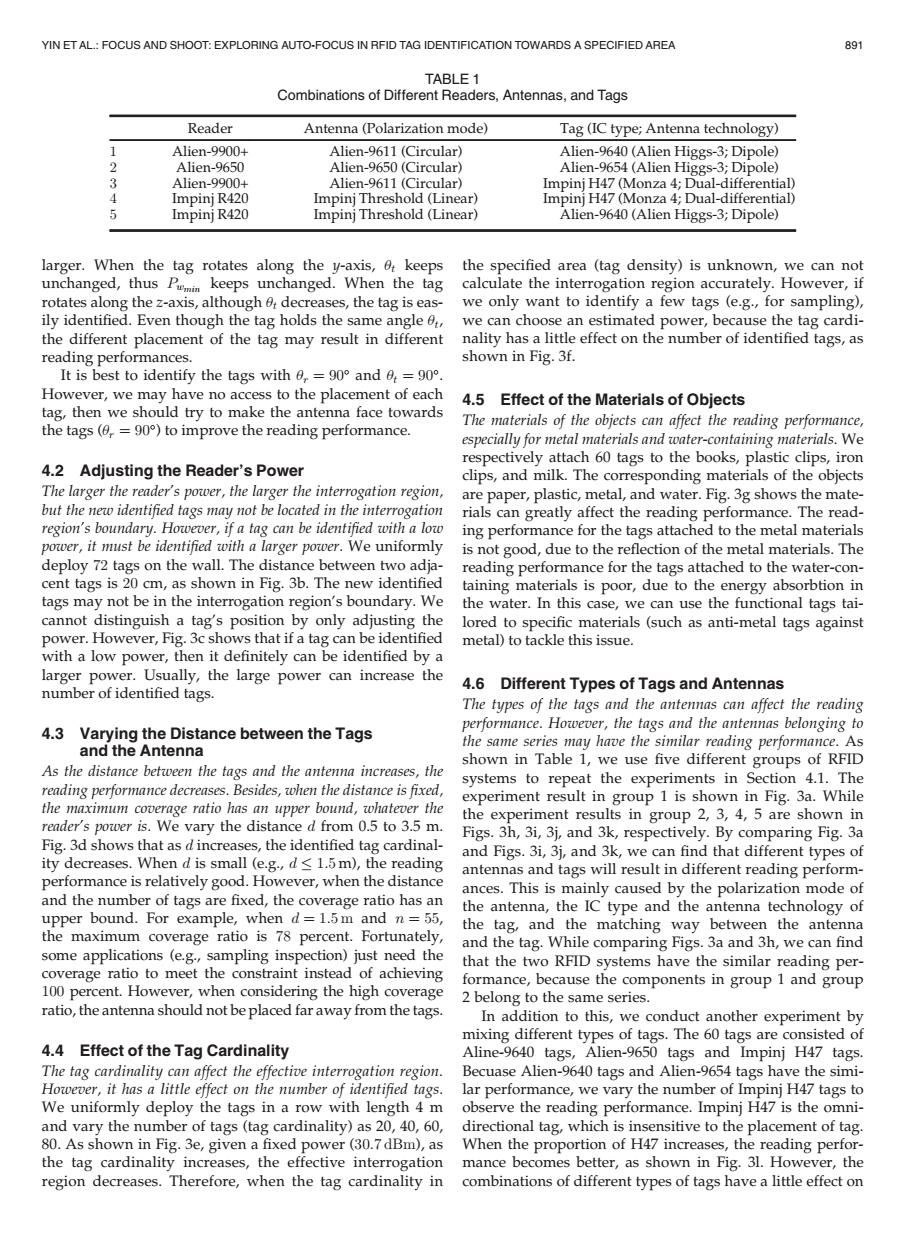
YIN ETAL:FOCUS AND SHOOT:EXPLORING AUTO-FOCUS IN RFID TAG IDENTIFICATION TOWARDS A SPECIFIED AREA 891 TABLE 1 Combinations of Different Readers,Antennas,and Tags Reader Antenna (Polarization mode) Tag(IC type;Antenna technology) Alien-9900+ Alien-9611(Circular) Alien-9640(Alien Higgs-3;Dipole) Alien-9650 Alien-9650(Circular) Alien-9654(Alien Higgs-3;Dipole) 3 Alien-9900+ Alien-9611(Circular) Impinj H47(Monza 4;Dual-differential) 4 Impinj R420 Impinj Threshold (Linear) Impinj H47(Monza 4;Dual-differential) Impinj R420 ImpinjThreshold (Linear) Alien-9640(Alien Higgs-3;Dipole) larger.When the tag rotates along the y-axis,0 keeps the specified area(tag density)is unknown,we can not unchanged,thus P keeps unchanged.When the tag calculate the interrogation region accurately.However,if rotates along the z-axis,although decreases,the tag is eas- we only want to identify a few tags (e.g.,for sampling), ily identified.Even though the tag holds the same angle we can choose an estimated power,because the tag cardi- the different placement of the tag may result in different nality has a little effect on the number of identified tags,as reading performances. shown in Fig.3f. It is best to identify the tags with 0,=90 and 6=90. However,we may have no access to the placement of each 4.5 Effect of the Materials of Objects tag,then we should try to make the antenna face towards the tags(0,=90)to improve the reading performance. The materials of the objects can affect the reading performance, especially for metal materials and water-containing materials.We respectively attach 60 tags to the books,plastic clips,iron 4.2 Adjusting the Reader's Power clips,and milk.The corresponding materials of the objects The larger the reader's power,the larger the interrogation region, are paper,plastic,metal,and water.Fig.3g shows the mate- but the new identified tags may not be located in the interrogation rials can greatly affect the reading performance.The read- region's boundary.However,if a tag can be identified with a low ing performance for the tags attached to the metal materials power,it must be identified with a larger power.We uniformly is not good,due to the reflection of the metal materials.The deploy 72 tags on the wall.The distance between two adja- reading performance for the tags attached to the water-con- cent tags is 20 cm,as shown in Fig.3b.The new identified taining materials is poor,due to the energy absorbtion in tags may not be in the interrogation region's boundary.We the water.In this case,we can use the functional tags tai- cannot distinguish a tag's position by only adjusting the lored to specific materials (such as anti-metal tags against power.However,Fig.3c shows that if a tag can be identified metal)to tackle this issue. with a low power,then it definitely can be identified by a larger power.Usually,the large power can increase the number of identified tags. 4.6 Different Types of Tags and Antennas The types of the tags and the antennas can affect the reading 4.3 Varying the Distance between the Tags performance.However,the tags and the antennas belonging to and the Antenna the same series may have the similar reading performance.As shown in Table 1,we use five different groups of RFID As the distance between the tags and the antenna increases,the systems to repeat the experiments in Section 4.1.The reading performance decreases.Besides,when the distance is fixed, experiment result in group 1 is shown in Fig.3a.While the maximum coverage ratio has an upper bound,whatever the the experiment results in group 2,3,4,5 are shown in reader's power is.We vary the distance d from 0.5 to 3.5 m. Figs.3h,3i,3j,and 3k,respectively.By comparing Fig.3a Fig.3d shows that as d increases,the identified tag cardinal- and Figs.3i,3j,and 3k,we can find that different types of ity decreases.When d is small (e.g.,d<1.5m),the reading antennas and tags will result in different reading perform- performance is relatively good.However,when the distance ances.This is mainly caused by the polarization mode of and the number of tags are fixed,the coverage ratio has an the antenna,the IC type and the antenna technology of upper bound.For example,when d=1.5m and n=55, the tag,and the matching way between the antenna the maximum coverage ratio is 78 percent.Fortunately, and the tag.While comparing Figs.3a and 3h,we can find some applications (e.g,sampling inspection)just need the that the two RFID systems have the similar reading per- coverage ratio to meet the constraint instead of achieving formance,because the components in group 1 and group 100 percent.However,when considering the high coverage 2 belong to the same series. ratio,the antenna should not be placed far away from the tags. In addition to this,we conduct another experiment by mixing different types of tags.The 60 tags are consisted of 4.4 Effect of the Tag Cardinality Aline-9640 tags,Alien-9650 tags and Impinj H47 tags. The tag cardinality can affect the effective interrogation region. Becuase Alien-9640 tags and Alien-9654 tags have the simi- However,it has a little effect on the number of identified tags. lar performance,we vary the number of Impinj H47 tags to We uniformly deploy the tags in a row with length 4 m observe the reading performance.Impinj H47 is the omni- and vary the number of tags (tag cardinality)as 20,40,60,directional tag,which is insensitive to the placement of tag 80.As shown in Fig.3e,given a fixed power (30.7 dBm),as When the proportion of H47 increases,the reading perfor- the tag cardinality increases,the effective interrogation mance becomes better,as shown in Fig.31.However,the region decreases.Therefore,when the tag cardinality in combinations of different types of tags have a little effect onlarger. When the tag rotates along the y-axis, ut keeps unchanged, thus Pwmin keeps unchanged. When the tag rotates along the z-axis, although ut decreases, the tag is easily identified. Even though the tag holds the same angle ut, the different placement of the tag may result in different reading performances. It is best to identify the tags with ur ¼ 90 and ut ¼ 90. However, we may have no access to the placement of each tag, then we should try to make the antenna face towards the tags (ur ¼ 90) to improve the reading performance. 4.2 Adjusting the Reader’s Power The larger the reader’s power, the larger the interrogation region, but the new identified tags may not be located in the interrogation region’s boundary. However, if a tag can be identified with a low power, it must be identified with a larger power. We uniformly deploy 72 tags on the wall. The distance between two adjacent tags is 20 cm, as shown in Fig. 3b. The new identified tags may not be in the interrogation region’s boundary. We cannot distinguish a tag’s position by only adjusting the power. However, Fig. 3c shows that if a tag can be identified with a low power, then it definitely can be identified by a larger power. Usually, the large power can increase the number of identified tags. 4.3 Varying the Distance between the Tags and the Antenna As the distance between the tags and the antenna increases, the reading performance decreases. Besides, when the distance is fixed, the maximum coverage ratio has an upper bound, whatever the reader’s power is. We vary the distance d from 0.5 to 3.5 m. Fig. 3d shows that as d increases, the identified tag cardinality decreases. When d is small (e.g., d 1:5 m), the reading performance is relatively good. However, when the distance and the number of tags are fixed, the coverage ratio has an upper bound. For example, when d ¼ 1:5 m and n ¼ 55, the maximum coverage ratio is 78 percent. Fortunately, some applications (e.g., sampling inspection) just need the coverage ratio to meet the constraint instead of achieving 100 percent. However, when considering the high coverage ratio, the antenna should not be placed far away from the tags. 4.4 Effect of the Tag Cardinality The tag cardinality can affect the effective interrogation region. However, it has a little effect on the number of identified tags. We uniformly deploy the tags in a row with length 4 m and vary the number of tags (tag cardinality) as 20, 40, 60, 80. As shown in Fig. 3e, given a fixed power (30:7 dBm), as the tag cardinality increases, the effective interrogation region decreases. Therefore, when the tag cardinality in the specified area (tag density) is unknown, we can not calculate the interrogation region accurately. However, if we only want to identify a few tags (e.g., for sampling), we can choose an estimated power, because the tag cardinality has a little effect on the number of identified tags, as shown in Fig. 3f. 4.5 Effect of the Materials of Objects The materials of the objects can affect the reading performance, especially for metal materials and water-containing materials. We respectively attach 60 tags to the books, plastic clips, iron clips, and milk. The corresponding materials of the objects are paper, plastic, metal, and water. Fig. 3g shows the materials can greatly affect the reading performance. The reading performance for the tags attached to the metal materials is not good, due to the reflection of the metal materials. The reading performance for the tags attached to the water-containing materials is poor, due to the energy absorbtion in the water. In this case, we can use the functional tags tailored to specific materials (such as anti-metal tags against metal) to tackle this issue. 4.6 Different Types of Tags and Antennas The types of the tags and the antennas can affect the reading performance. However, the tags and the antennas belonging to the same series may have the similar reading performance. As shown in Table 1, we use five different groups of RFID systems to repeat the experiments in Section 4.1. The experiment result in group 1 is shown in Fig. 3a. While the experiment results in group 2, 3, 4, 5 are shown in Figs. 3h, 3i, 3j, and 3k, respectively. By comparing Fig. 3a and Figs. 3i, 3j, and 3k, we can find that different types of antennas and tags will result in different reading performances. This is mainly caused by the polarization mode of the antenna, the IC type and the antenna technology of the tag, and the matching way between the antenna and the tag. While comparing Figs. 3a and 3h, we can find that the two RFID systems have the similar reading performance, because the components in group 1 and group 2 belong to the same series. In addition to this, we conduct another experiment by mixing different types of tags. The 60 tags are consisted of Aline-9640 tags, Alien-9650 tags and Impinj H47 tags. Becuase Alien-9640 tags and Alien-9654 tags have the similar performance, we vary the number of Impinj H47 tags to observe the reading performance. Impinj H47 is the omnidirectional tag, which is insensitive to the placement of tag. When the proportion of H47 increases, the reading performance becomes better, as shown in Fig. 3l. However, the combinations of different types of tags have a little effect on TABLE 1 Combinations of Different Readers, Antennas, and Tags Reader Antenna (Polarization mode) Tag (IC type; Antenna technology) 1 Alien-9900+ Alien-9611 (Circular) Alien-9640 (Alien Higgs-3; Dipole) 2 Alien-9650 Alien-9650 (Circular) Alien-9654 (Alien Higgs-3; Dipole) 3 Alien-9900+ Alien-9611 (Circular) Impinj H47 (Monza 4; Dual-differential) 4 Impinj R420 Impinj Threshold (Linear) Impinj H47 (Monza 4; Dual-differential) 5 Impinj R420 Impinj Threshold (Linear) Alien-9640 (Alien Higgs-3; Dipole) YIN ET AL.: FOCUS AND SHOOT: EXPLORING AUTO-FOCUS IN RFID TAG IDENTIFICATION TOWARDS A SPECIFIED AREA 891